Download
1 / 49
490 likes | 611 Views
Balancing Uplink and Downlink Delay of VoIP Traffic in 802.11 WLANs. Sangho Shin Henning Schulzrinne Columbia University Department of Computer Science. Motivation. VoIP in IEEE 802.11 WLANs. Distribution Network (DS). Access Point (AP). STAs. 1/30. Motivation.

E N D
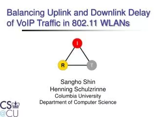
Balancing Uplink and Downlink Delay of VoIP Traffic in 802.11 WLANs Sangho Shin Henning Schulzrinne Columbia University Department of Computer Science
Motivation • VoIP in IEEE 802.11 WLANs Distribution Network (DS) Access Point (AP) STAs 1/30
Motivation • VoIP in IEEE 802.11 WLANs Distribution Network (DS) Access Point (AP) STAs 1/30
Motivation • VoIP in IEEE 802.11 WLANs Distribution Network (DS) Access Point (AP) STAs 1/30
Motivation Downlink Uplink 20 ms packetization interval (64kb/s) 2/30
Motivation • When the channel is congested …. Distribution Network (DS) Queue Queue Queue Queue Queue 3/30
Motivation • When the channel is congested …. Distribution Network (DS) Queue Queue Queue Queue Queue 3/30
Motivation • When the channel is congested …. Distribution Network (DS) Queue Queue Queue Queue Queue 3/30
Motivation • When the channel is congested …. Distribution Network (DS) Queue Queue Queue Queue Queue 3/30
Motivation • When the channel is congested …. Distribution Network (DS) Queue Queue Queue Queue Queue 3/30
Motivation • Solutions? Give a higher priority to the AP than STAs Distribution Network (DS) Queue Queue Queue Queue Queue 4/30
Outline • Background • Adaptive Priority Control (APC) • Simulation results • Implementation Issues • Conclusions • Future work 5/30
Contention Window DIFS DIFS Busy Medium Backoff Frame Defer Access Slot time Background • Medium Access in DCF (Distributed Coordination Function) Number of Backoff = (0, CWmin) 6/30
Background • How to control the priority of the AP? • Inter-Frame Spacing (IFS) • Contention Window (CW) • Contention Free Transmission Contention Window DIFS DIFS Busy Medium Backoff Frame Defer Access Slot time 7/30
Number of Backoff = (0, CWmin) DIFS Backoff Frame1 DIFS Backoff Frame2 DIFS Backoff Frame3 Number of Backoff = (0, CWmin/2) DIFS BO Frame1 DIFS BO Frame2 DIFS BO Frame3 Transmission Control • Control Contention Window (CW) Remaining BO time BO BO STA DIFS BO1 Defer Access DIFS BO2 Defer Access DIFS BO Frame AP DIFS BO Frame DIFS BO Frame DIFS BO Defer Access 8/30
Transmission Control • Control Contention Window (CW) • It is hard to control the priority accurately. • Backoff time is randomly decided between (0, CWmin). • Shorter CW Higher collision probability • Decrease the capacity. 9/30
IFS = DIFS DIFS Backoff Frame1 DIFS Backoff Frame2 DIFS Backoff Frame3 IFS = DIFS/2 IFS Backoff Frame1 IFS Backoff Frame2 IFS Backoff Frame3 Transmission Control • Control IFS Frame STA1 STA2 Defer Access DIFS BO Defer Access DIFS Frame AP Defer Access IFS BO Frame 10/30
IFS Frame1 IFS Frame2 IFS Frame3 P = 3 IFS Frame1 IFS Frame2 IFS Frame3 DIFS BO Defer Access P = 2 IFS Frame1 IFS Frame2 DIFS BO Defer Access IFS Frame3 Transmission Control • Contention Free Transmission (CFB) • Control the number of frames (P) 11/30
Transmission Control • Contention Free Transmission (CFB) • Precise priority control • P Priority • Transmitting three frames contention free three times higher priority than other STAs. • No overhead 12/30
Adaptive Priority Control • Optimal priority of the AP to balance the uplink and downlink delay ? • Number of active wireless STAs Semi-Adaptive Method 13/30
Semi-Adaptive 10 packets P = 4
Semi-Adaptive 6 packets P = 4
Adaptive Priority Control • Optimal priority of the AP to balance the uplink and downlink delay ? • Number of active wireless STAs Semi-Adaptive Method • Simple • Adaptive to the change of the number of active wireless STAs. • Not adaptive to the change of the traffic volume of uplink and downlink. 13/30
10 packets 2 packets P = 4 P = 4 Semi-Adaptive
Network Queuing dely Adaptive Priority Control • Optimal priority of the AP to balance the uplink and downlink delay ? • Uplink/Downlink delay ≈Queuing delay • The same packet processing time in Queue of the AP and STAs The same queuing delay Access delay Propagation delay 14/30
Adaptive Priority Control • Optimal Priority = QAP/QSTA (QSTA>0) 15/30
APC 10 packets P = 10 / 2 = 5
APC 10 packets P = 10 / 2 = 5
APC 5 packets P = 5/1 = 5
Adaptive Priority Control • Optimal Priority = QAP/QSTA • Simple • Adaptive to change of number of active STAs • Adaptive to change of uplink/downlink traffic volume • Results in the same packet processing time between the AP and STAs same queuing delay in the AP and STAs same uplink and downlink delay 15/30
Downlink Uplink 20 ms packetization interval (64kb/s) Simulation Results - DCF 2/30
Semi-Adaptive Method Simulation Results 20 ms packetization interval (64kb/s) 16/30
Simulation Results - APC 20 ms packetization interval (64kb/s) 17/30
Simulation Results APC vs Semi-Adaptive Semi-Adaptive APC 20 ms packetization interval (64kb/s) 18/30
30% Simulation Results DCF vs APC DCF APC Capacity = 28 Capacity = 35 20 ms packetization interval (64kb/s) 19/30
Simulation Results - APC 20/30
Simulation Results Semi-Adaptive Method 10ms + 20 ms packetization interval (64kb/s) 21/30
Simulation Results - APC 10ms + 20 ms packetization interval (64kb/s) 22/30
Simulation Results APC vs Semi-AdaptiveMethod APC Semi-Adaptive 10ms + 20 ms packetization interval (64kb/s) 23/30
Simulation Results - APC 40 ms packetization interval (64kb/s) 24/30
Simulation Results - APC 20 ms + 40 ms packetization interval (64kb/s) 25/30
Implementation Issues • How can the AP know the queue size of nodes? • Add the queue size of each node to VoIP packets. • It requires the changes in clients • Estimate the average queue size of nodes • Queue size = Number of packets generated at APP layer – Number of packets transmitted • Number of packets transmitted ≈ Number of packets received • Number of packets generated at APP layer ≈ Number of active nodes x packetization interval 26/30
Implementation Issues • How to implement Contention Free Transmission? • IEEE 802.11e : Contention Free Bursty (CFB) • Change the CFB duration. • Wireless Media Extension (WME) • A subset of IEEE 802.11e • Implemented in many chipsets • Allows change of IFS, CFB duration 28/30
Conclusions • Uplink and downlink delay VoIP traffic in DCF are significantly unbalanced. • APC, in which AP transmits QAP/QNodes packets, balances the uplink and downlink delay. • APC improves the capacity for VoIP traffic from 28 calls to 35 calls, by 25%. 29/30
Future Work • Integrate APC to IEEE 802.11e. • Measure the performance of APC with background traffic. • Measure the performance of APC with actual wireless nodes in ORBIT test-bed. 30/30
Thank you Questions?
Motivation • VoIP in IEEE 802.11 WLANs Distributed Network (DS)
0.23 1.0 0.5 0.9 0.3 1.5 Simulations • VoIP traffic model • ITU-T P59 • Our Model