Drilling Engineering – PE311 Circulating System
620 likes | 1.83k Views
Drilling Engineering – PE311 Circulating System. Circulating System in Drilling. Circulating System in Drilling.

Drilling Engineering – PE311 Circulating System
E N D
Presentation Transcript
Drilling Engineering – PE311 Circulating System
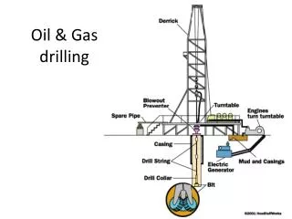
Circulating System in Drilling The drilling mud travels up the stand pipe and through the rotary hose, and then downward through the kelly or top drive system, drill pipe and bottomhole assembly by the mud pumps. It exists the drill string through the bit nozzles and picks up drill cuttings from the bottom of the hole. It then carries the cuttings up the annulus, past the blowout preventers, and through the mud-return line to the shale shaker. At the shale shaker, the larger cuttings are screened out and diverted to a "reserve pit" (actually a waste pit). Desanders, desilters and centrifuges may be used to filter out smaller particles. The mud flows into a settling tank or pit and finally, it returns through the sump to the suction pit to repeat the circuit.
Auxiliary System Drilling fluid maintenance system There are two types of auxiliary systems associated with the basic circulating system: the drilling fluid maintenance system and the well pressure control system. The drilling fluid maintenance system includes the shale shaker (a set of rotating or vibrating screens, which removes the larger drill cuttings from the returning mud and serves as the sampling point for drill-cuttings analysis); mud guns and mud-pit agitators for maintaining a uniform content of mud solids; cone-type desanders, desilters, and centrifuges to remove contaminants that would not otherwise settle out; and a mud-gas separator and vacuum degasser for removal of entrained gases.
Auxiliary System Drilling fluid maintenance system Shale Shaker
Auxiliary System Drilling fluid maintenance system Desilters and Desanders: The desilters/desanders must be equipped with centrifugal pumps capable of providing sufficient pressure to the hydrocyclones to allow them to operate in the desired pressure range.
Auxiliary System Drilling fluid maintenance system http://www.youtube.com/watch?v=82VXx-tEpnQ
Auxiliary System Well pressure control system The main components of the wellpressure control system is the blowout preventers (BOPs), which are located under the rig floor on the casing head. A blowout preventer is a large, specialized valve used to seal, control and monitor oil and gas wells. Blowout preventers were developed to cope with extreme erratic pressures and uncontrolled flow emanating from a well reservoir during drilling.
BOPs A ram-type BOP uses a pair of opposing steel plungers, rams. The rams extend toward the center of the wellbore to restrict flow or retract open in order to permit flow. The inner and top faces of the rams are fitted with packers (elastomeric seals) that press against each other, against the wellbore, and around tubing running through the wellbore. Outlets at the sides of the BOP housing (body) are used for connection to choke and kill lines or valves.
BOPs Pipe rams (Annular preventer) close around a drill pipe, restricting flow in the annulus between the outside of the drill pipe and the wellbore, but do not obstruct flow within the drill pipe. Blind rams which have no openings for tubing, can close off the well when the well does not contain a drill string or other tubing, and seal it. Shear rams cut through the drill string or casing with hardened steel shears. Kill line: permits mud to be pumped down to the annulus to restore a pressure balance Choke line: Annular pressure relief lines http://www.youtube.com/watch?v=kBQdTv7bspM
Mud Pumps The mud pumps are the heart of the circulating system, providing power to move the fluid at the required pressure and volume. Mud pumps are either duplex (two-cylinder) or triplex (three-cylinder). Triplex pumps are by far the type most commonly used on modern rigs.
Triplex Pumps – Single Acting Triplex pumps have three cylinders, and are generally single-acting pumps
Triplex Pumps – Single Acting As the plunger (A) moves to the right, the fluid is compressed until its pressure exceeds the discharge pressure, and the discharge check valve (B) opens. The continued movement of the plunger to the right pushes liquid into the discharge pipe. As the plunger begins to move to the left, the pressure in the cylinder becomes less than that in the discharge pipe, and the discharge valve (B) closes. Further movement to the left causes the pressure in the cylinder to continue to decline until it is below suction pressure. At this point the suction check valve (C) opens. As the plunger continues to move to the left, the cylinder fills with liquid from the suction. As soon as the plunger begins to move to the right, it compresses the liquid to a high enough pressure to close the suction valve (C), and the cycle is repeated.
Pump Factor – Single acting The volume displaced by each piston during one complete pump cycle is given by The pump factor for a single-acting pump having three cylinders becomes The flow rate Where N is the number of stroke per unit time Hydraulic power Dp, psi and Q, GPM dr
Duplex Pumps – Double Acting Duplex pumps have two cylinders, and are generally double-acting pumps
Duplex Pumps – Double Acting Duplex pumps are double-acting, with two cylinders. Each of the two cylinders is filled on one side of the piston at the same time that fluid is being discharged on the other side of the piston. With each complete cycle of a piston, mud is discharged at twice the volume of the cylinder minus the volume of the piston rod. When the piston moves to the right, the liquid in the cylinder to the right of the piston (E) is discharged, and the cylinder to the left of the piston (F) is filled. When the direction of the piston is reversed, the liquid in F is discharged, and the cylinder at E is filled with suction fluid. Thus, liquid is pumped when the piston moves in either direction.
Pump Factor – Double Acting On the forward stroke of each piston, the volume displaced is given by On the backward stroke of each piston, the volume displaced is given by Thus, the total volume displaced per complete pump cycle by a pump having two cylinders is given by The flow rate
Example Consider a triplex pump having 6-in liners and 11-in strokes operating at 120 cycles/min and a discharge pressure of 3000 psig. Compute Pump factor in units of gal/cycle at 100% volumetric efficiency Flow rate in gal/min Pump power developed
Example Pump factor in units of gal/cycle at 100% volumetric efficiency 2. Flow rate in gal/min 3. Pump power developed