Download
1 / 20
200 likes | 228 Views
This study analyzes the Beam Diagnostic System in HIRFL-CSRm at IMP, China for the Bunched Electron Cooling Demo Experiment. It includes parameters, layout, and performance specifications of the EC-35 cooler and electron beam characteristics. The text also discusses the proposed experiment parameters, RF modulation, and DC bias scheme for bunched electron beam formation. Furthermore, it covers the simulation and experiments related to beam formation and improvements for reduced transversal instability of the cooled ion beam. The analysis includes the description of existing and modified BPM devices for beam diagnostics along with recommendations for resonant circuit design and beam current measurement techniques. The analysis emphasizes the importance of improving sensitivity and signal-to-noise ratio for effective data sampling and signal processing in the cooling experiment.

E N D
Beam Diagnostic System Analysis in HIRFL-CSRm at IMP, China for the Bunched Electron Cooling Demo Experiment Haipeng Wang Lijun Mao (Experiment) at IMP and Yuhong Zhang, (LDRD 2014 PI) and He Zhang (Cooling Simulation) at JLab Thanks also for contribution from Jie Li, Xiaoming Ma, and He Zhao, IMP, China and ChinaVasily Parkhomchuk and Vladimir Reva1, BINP, Russia
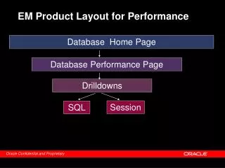
HIREL-CSR Layout and Performance Specification EC-35 cooler
EC-35 DC Cooler and Commissioned Performance 1—electron gun, 2—electrostatic bending plates, 3—toroid, 4—solenoid of cooling section, 5—magnet platform, 6—collector for electron beam, 7—dipole corrector, 8—vacuum flange for CSRm. Two BPMs placed in the cooling station, one is at upstream of electron beam at gun side in position 9, another one is at downstream collector side in the mirror symmetric position relative to 9. Commissioned in March 2003 • vacuum 21011 mbar, • high voltage 20 kV, • electron beam current 1.6 A, • collector efficiency >99.99%, • angle of magnetic field line in cooling section <210-5
Terminal Circuit Diagram and Average Current Measurement electrons ions Collector efficiency
EC-35 RF Modulation + DC Bias Scheme for Bunched Electron Beam Formation bunch length fm3 MHz
Beam Diagnostic Devices for Bunched Electron Cooling Demo Experiment • existing • modification • new installation
RF Amplifier Resonant Circuit Design, Prototype and test Result Courtesy of Dr. L.J. Mao, IMP Bench prototype circuit simulations Output voltage and impedance measurements
Electron Gun Simulation by CST EM-Static and PS Tracking Solvers E-field-am E-potential Hollow beam Solid beam
Solid to Hollow Beam Formation in Simulation and Experiments • Reduction of transversal instability of cooled ion beam. It may be achieved by using the electron beam with the density increasing radially but low at the center. • Problems arisen due to space charge effect may be partially solved by using the hollow electron beam with low transversal electric field near its center. • Reduction of the effect of recombination between the accumulated ions and the electron beam. • Suppress the electron heating effect in the center
Capacitive Beam Pickup Principles and Sensitivity to Beam Current Our bunched beam electron cooling experiment is at the range of 0.121~0.247. So either type of the pickup is OK for the BCM For RCs <<1, fm<<fc, R is preferred in low resistance for high roll-off frequency fc. Too weak! We need to modify the external circuit of BPM to be a resonant circuit in order to improve the bunch edge sensitivity and S/N ratio.
Modification Suggestion to Existing BPM External Circuits to BCM • Can tune harmonic of the ion accelerating frequency f0 and electron modulation frequency fm separately on different BPMs if not synchronized • Detune due to the resistive loss is small and the inductance can be compensated by a tunable inductor element. • Bunch beam charging time t >> the resonance RLC circuit (or cavity) filling time Q/r. Say 2 times at least. So the induced voltage V(t) will not drop between the bunches 1/f0-t. • Data sampling rate fs has to be fast enough to resolve the bunch rise time scale of ~10ns.
1D Signal Calculation for Square Bunch and Ring-shape Pickup Electron (red solid line) and ion (green solid line) bunch signals picked up by modified capacitive type BCM plates and their bunch shapes (dashed red line for electron, dashed green line for ion) calculated by MathCAD program for =0.121, average beam currents of 70mA for electron and 3mA for 12C+6. The voltage signal is picked up on the total shunt resistor of R=150. The voltage signal gain on the ion current is 40dB (80dB in power) for this display. In this calculation example, there are 7 electron bunches with in one ion bunch.
1D Signal Calculation for Gaussian Bunch and Ring-shape Pickup Gaussian bunch shape distribution (black) in 7ns (rms) bunch length current picked up by 50 W shunt impedance’s voltage (red, calculation) and comparison to the experimental data (blue) for one of 12C+6 bunches accelerated in the CSRm ring at the 0.5 velocity. The blue data is measured by a fast oscilloscope on a Ls=15cm pickup cylinder. The voltage gain of such signal is ~350. The ion current is ~3mA. Signal ringing on the back is due to the pickup circuit.
Using Longitudinal Schottky Diodes to Measure the Cooling Rates Courtesy of Dr. L.J. Mao, IMP
Summary • Bunched electron Beam Cooling Demo Experiment at IMP has been proposed in 2014 at JLab and carried out by the collaboration team at 2015 with JLab LDRD fund and IMP internal fund. • HV power supplies and RF amplifier hardware are under commissioning for the electron beam modulation scheme • Demo experiment is scheduled in 2016 • Modification of IMP CSRm BPM system into a BCM measurement device to measure the beam bunch length and peak current is possible for our demo bunched electron cooling experiment • Using existing EC-35 BPM system, a minor circuit modification (or using sum/diff. combined signals) using a resonant circuit is possible for the electron bunch length and shape measurement • Modification to resonant Schottky, using Palmer pickup devices (in CSRs ring only), extraction kicker in CSRe ring (under the study) for the ion beam bunch length and current measurement will greatly increase the S/N ratio. The new BCM circuit design parameters have been specified. • EC-35 Cooler and CSRm ring can do all of these schemes for the demo experiment: DC to coasting, bunch to coasting and bunch to bunch, synchronization and non-sychronization
References [1] Yuhong Zhang, He Zhang, et al JLab LDRD 2014 proposal, funded in FY2015. [2] CSR Design Group, “CSR Storage Ring Parameters List”, HIRFL-CSR/General/02-1, January 25, 2002, Submitted by J.W. Xia. [3] Li Guo-Hong, etc. “A Beam Position Monitor System for Electron Cooler in HIRFL 2 CSR (in Chinese)”, Nuclear Physics Review, Issue 1, Vol. 27, March, 2010, Article No. 1007 - 4627 (2010) 04 - 0043 – 05. [4] V. Bocharov et al. “HIRFL-CSR electron cooler commissioning”, Nuclear Instruments and Methods in Physics Research A 532 (2004) 144–149. [5] E. Bekhtene, L.J. Mao, H. Wang and Y. Zhang, the discussion of bunched beam formation by the RF modulation scheme in the MEIC collaboration meeting in March, 2014. [6] L.J.Mao et al, “Longitudinal electron cooling experiments at HIRFL-CSRe”, to be published in 2015. [7] A.V. Bubley et al. “Measuring a hollow electron beam profile”, Nuclear Instruments and Methods in Physics Research A 532 (2004) 413–417. [8] A.V. Bubley et al, “The Electron Gun with Variable Beam Profile for Optimization of Electron Cooling”, Proceedings of EPAC 2002, Paris, France, WEPRI049. [9] G. R. Lambertson, Dynamic Devices – Pickups and Kickers, LBL-22085, BECON-63, LBL, UC Berkeley, August, 1986. [10] D. A. Goldberg and G. R. Lambertson, Dynamic Devices, A Primer on Pickups and Kickers LBL-31664, November, 1991. [11] Strehl P. Beam Instrumentation and Diagnostics. Berlin Heidelberg : Springer , 2006 , 155-211. [12] Phone meeting conversation between Haipeng Wang, He Zhang and Yuhong Zhang at JLab with Lijun Mao at IMP on August 5, 2015. [13] Strehl, P., Klabunde, J., Schaa, V., Vilhjalmsson, H., Wilms, D., Das Phasen-sondensystem am Unilac : Sondendimensionierung und Signalauswertung, GSI-Report 79–13, (1979), translated for the Los Alamos Scientific Laboratory by Leo Kanner Associates, Redwood City, (1980), LA-TR-80–43. [14] JLab technote publication JLab-TN-15-039.