Announcements
Announcements. Assignment 1 solutions posted Assignment 2 due Thursday First mid-term Thursday October 27 th (?). Lecture 8 Overview. Inductors in transient circuits Semiconductors Diodes Rectifying circuits Other Diode Applications Transistors. Time response of Inductors.


Announcements
E N D
Presentation Transcript
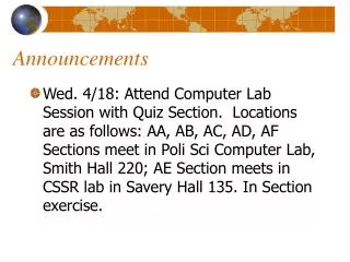
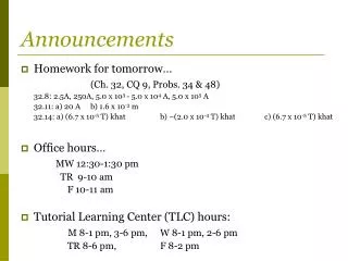
Announcements • Assignment 1 solutions posted • Assignment 2 due Thursday • First mid-term Thursday October 27th (?)
Lecture 8 Overview • Inductors in transient circuits • Semiconductors • Diodes • Rectifying circuits • Other Diode Applications • Transistors
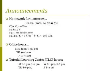
Time response of Inductors Switch to position a: Integrate and apply boundary condition t=0, i=0 Time constant τ=L/R. Talk about "Charging a capacitor" "Current build-up" in an inductor Switch to position b:
Time response of Inductors A battery is connected to an inductor. When the switch is opened does the light bulb: 1.Remain off 2.Go off 3. Slowly Dim out 4. Keep burning as brightly as it did before the switch was opened 5. Flare up brightly, then dim and go out Answer 5
Semiconductors Simple review of basic concepts: What is a semiconductor? (for more detail see e.g. Simpson Ch. 4) Elements such as Silicon and Germanium have 4 valence electrons in their outer shell They form covalent bonds with neighbouring atoms to form strong crystal lattice structures. In pure silicon, all valence electrons are bound in the lattice structure
depletion region E-field (~0.2V Ge, ~0.5V Si) Semiconductors The addition of impurities ("doping"), such as Sb(Antimony) with 5 valence electrons, leaves one electron unbound and free to move and create a current flow (n-type semiconductor). Alternatively, an impurity with 3 valence electrons can be used to create positive "holes". When a p-type and an n-type are joined (p-n junction), mobile electrons diffuse from the n-type to the p-type, forming positive and negative ions at fixed positions in a state of equilibrium which inhibit further transfer of electrons (depletion region) - +
What happens when you apply a voltage? For the device to conduct, electrons from the n-type region must cross the junction Depletion region E-field Reverse bias: Apply an electric field in this direction, mobile electrons are driven away from the junction (unlike fixed charged ions). Mobile holes are also driven away in the opposite direction. Depletion region acts like an insulating slab - No current flows applied E-field Depletion region E-field Forward bias: Helps electrons overcome the depletion region. Current flows easily applied E-field
Ideal diode • A diode is a non-linear circuit element • Only passes current in one direction • Constructed from a p-n semiconductor junction
Real diode Diode law: IS = reverse-leakage current v = voltage across the diode kB = Boltzmann's constant e- = electron charge T = Temperature (K) Strong dependence on T IS is small ~ 10-6A (Ge), ~10-8(Si)
Diode Circuit • Diodes are non-linear; how do we calculate the operating conditions? (Can’t easily use V=IR) • Consider the simplest diode circuit KVL: When ID=0; VD=VDD When VD=0; ID=VDD/R Must satisfy both equations: Operating point can be calculated by seeing when diode law line intersects load line
Rectifying Circuit Ideal transformer: VS/VP=NS/NP Real transformers are ~98% efficient One of the most important applications of a diode is in rectifying circuits: used to convert an AC signal into the DC voltage required by most electronics
Half-wave rectifier • Only lets through positive voltages. Rejects negative voltages
- - + - + + Full-wave rectifier • To use both halves of the input sinusoid,can use a centre-tapped transformer: e.g. Battery Charger
or use a Bridge rectifier • Does not require centre-tapped transformer • Requires 2 diodes in each direction – cheap, but voltage drop is double
Bridge rectifier • Current flow in the bridge vO vO + - - +
Peak rectifier • Most devices need steady DC • To smooth out the peaks and obtain a DC voltage When source voltage < capacitor voltage Diode is reversed biased Capacitor discharges through resistor
Another diode application: Voltage doubler • High Voltage transformers are expensive and impractical at voltages above a few thousand Volts. How do we get higher? C1 charges to 2Vsec C2 charges to Vsec
Voltage doubler • Can extend this circuit to produce extremely high voltages (~750kV). • Cockroft-Walton voltage multiplier • 1932, Cavendish Labs • reached 250 kV • Accelerated protons onto a Lithium target • Split the atom! • http://www.youtube.com/watch?v=RdBqMtioh6U Voltage Quadrupler