Download
1 / 29
330 likes | 585 Views
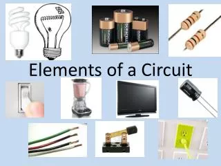
Lumped Modeling with Circuit Elements, Ch. 5, Text. Ideal elements represent real physical systems. Resistor, spring, capacitor, mass, dashpot, inductor… To model a dynamic system, we must figure out how to put the elements from different domains together.

E N D
Lumped Modeling with Circuit Elements, Ch. 5, Text • Ideal elements represent real physical systems. • Resistor, spring, capacitor, mass, dashpot, inductor… • To model a dynamic system, we must figure out how to put the elements from different domains together. • Alternatives include numerical modeling of the whole system. Lumped element modeling offers more physical insight and may be necessary for timely solutions.
Example. Electrical: Resistor-Inductor-Capacitor (RLC) system. C No power source, transient response depends on initial conditions R L i B1, B2 depend on initial conditions
Example. Mechanical: Spring-Mass-Dashpot system. x No power source, transient response depends on initial conditions k m B1, B2 depend on initial conditions b
Equations are the same if: 1/k b m . k 1/C x . I <-> x L m or C R b R L
Goal: Simulate the entire system. • Usual practice: • Write all elements as electrical circuit elements. • Represent the intradomain transducers (Ch. 6) • Use the powerful techniques developed for circuit analysis, linear systems (if linear), and feedback control on the whole MEMS system.
Senturia generalizes these ideas. • Introduce conjugate power variables, effort, e(t), and flow, f(t). • Then, generalized displacement, q(t) • And generalized momentum, p(t) e . f has units of power e . q has units of energy p . f has units of energy
Variable Assignment Conventions • Senturia uses e -> V, that is, effort is linked with voltage in the electrical equivalent circuit. He explains the reasons (for example potential energy is always associated with energy storage in capacitors).
Following Senturia’s e -> V convention: • For effort source, e is independent of f • For flow source, f is independent of e • For the generalized resistor, e=e(f) or f=f(e) • Linear resistor e=Rf • Electrical, V=RI • Mechanical, F=bV
For the generalized capacitor (potential energy): • For a linear electrical capacitor: ε – permitivity A – area G – Gap
The mechanical equivalent is the linear spring. (Check in table.) Cspring = 1/k
Generalized Inductor or inertance (kinetic energy?) Linear inertance: momentum flow momentum? m – mass v – velocity p – momentum Electrical? But what is this??? ???