Download

1 / 60
600 likes | 752 Views
Let ’ s talk about how to build stuff mockup p rototype m ass production Craig Forest. References: Product design for manufacture and assembly (G. Boothroyd et al. (Dekker 1994) Boothroyd and Dewhurst Kalpakjian, Manufacturing Engineering and Technology

E N D
Let’s talk about how to build stuff mockup prototype mass production Craig Forest References: Product design for manufacture and assembly (G. Boothroyd et al. (Dekker 1994) Boothroyd and Dewhurst Kalpakjian, Manufacturing Engineering and Technology Ullman, The Mechanical Design Process Gutowski, 2.810, MIT, 2002
Metal Band saw Drill press Mill Lathe Grinder Waterjet 3-D printing (laser sintering) Welding Casting Electrical discharge machining Sheet metal forming (shear, brake, corner press) Polymers 3-D printing Injection molding Thermoforming Laser cutting Casting Band saw Drill press Mill Lathe Waterjet Ceramics Molded and bakes, sintered Composites Layups Prototype manufacturing processes
Metal Band saw Drill press Mill Lathe Grinder Waterjet 3-D printing (laser sintering) Welding Casting Electrical discharge machining Sheet metal forming (shear, brake, corner press) Polymers 3-D printing Injection molding Thermoforming Laser cutting Casting Band saw Drill press Mill Lathe Waterjet Ceramics Molded and bakes, sintered Composites Layups Prototype manufacturing processes • Machining • Machining
Waterjet http://web.mit.edu/2.972/www/reports/abrasive_water_jet/abrasive_waterjet.html http://en.wikipedia.org/wiki/Water_jet_cutter www..omax.com
Laser cutting 75W CO2 laser 100 µm laser spot size 200 µm hole diameter Trotec Speedy 100
3D printing Layer by layer additive process http://home.att.net/~castleisland/sl.htm http://common.ziffdavisinternet.com/encyclopedia_images/_3DPCOLR.JPG http://www.archinect.com/schoolblog/entry.php?id=34570_0_39_0_C
Electrical discharge machining Wire as small as 30 µm! MS Thesis MIT 2003, Tim Fofonoff http://www.engineersedge.com/edm.shtml
Welding • Melt workpieces and add filler • Energy comes from gas flame, an electric arc, a laser, an electron beam, friction, and ultrasound Oxyacetylene ( 3100C ) -most common -cheap equipment http://en.wikipedia.org/wiki/Oxy-fuel_welding_and_cutting http://www.thenewchinkyworkshop.com/OxyAcetylene1.jpg
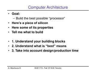
Machining http://www.efunda.com/processes/machining/machin_intro.cfm
Design rules for machining Standardization • Utilize standard components as much as possible • Preshape the component, if appropriate, by casting, forging, welding, etc • Utilize standard pre-shaped workpieces if possible • Employ standard machined features whenever possible.
Design rules for machining Raw Material • Choose raw material that results in minimum component cost (raw material + machining) • Utilize raw material in the standard forms supplied
Component design for machining Generally • Strive for machining using 1 machine tool • Strive to minimizing fixturing • Sufficient rigidity when fixtured for machining • No interference between tool, toolholder, workpiece, fixture • Holes cylindrical, straight and with standard L/D for drilling or boring, normal to part axes • Blind holes conical, tapping blind hole considered
Component design for machining Rotational components • Cylinders concentric, plane surfaces normal to axes • External diameters increase from outer face • Internal diameter decrease from outer face • For internal corners, use standard radii • Avoid intenal features for long components
Component design for machining Non-rotational components • Provide base for fixturing/referencing • Prefer faces perpendicular/parallel to base • Use standard radii, large radii for internal features • Diameters decrease inside the part
Accuracy and surface finish • Specify widest tolerances possible • Specify roughest surfaces possible • Avoid internal corners on low roughness surfaces
Sheet metal forming shearing bending drawing
Name 5 sheet metal formed parts • What materials are used • What can go wrong when sheet metal forming?
Sheet metal forming shearing bending
Design rules • Outer profile with parallel edges defining part width • Angles > 15˚ Features a-e >2x thickness Relief cutout
Design rules >2h >4h >2h
Design rules Minimize waste
$$$$ • Assembly costs are 25-50% of mfg costs • % workers doing assembly is 20-60% This is a big $$$ deal!!!
History lesson • 1st complex assembly mfg tasks • Muskets in 1700’s • Interchangeable parts in early 1800’s John Hall’s breech design demonstrated interchangeability at Harper’s Ferry in 1827
Complex products required more assembly >1,000 parts
>10,000 parts The Pratt & Whitney F100 military engine powered the F-15 and the F-16. Credits - Credit to Pratt & Whitney: A United Technologies Company >100,000 parts Airbus A380 for 853 people
Assembly line-Henry Ford Trained workers put together the flywheel - magneto ignition system for the Model T - 1913 The old fashioned way - limousines areassembled at individual stationsby a Pittsburg manufacturer, 1912 End of the Line. The Model T's body is joinedto its chassis at the Highland Park plant
Requirements • Work design (balance steps, ergonomics) • Design for assembly • Interchangeable parts
Manual Automated High-speed automated assembly Robotic assembly Handling Pickup Orient Insertion Location Hold down and resistance Securing method Assembly types
Design for Manual Assembly Rules • Reduce part count and part types • Strive to eliminate adjustments • Design parts to be self-aligning and self-locating • Ensure adequate access and unrestricted vision • Ensure the ease of handling of parts from bulk • Minimize the need for reorientations during assembly • Design parts that cannot be installed incorrectly • Maximize part symmetry if possible or make parts obviously asymmetrical
8. Maximize part symmetry if possible or make parts obviously asymmetrical
Automatic part handling Be easily separated from bulk Be easily conveyed along the track of a vibratory or hopper feeder Be readily oriented in high speed feeding device Automatic insertion Avoid need to reorient during assembly Parts not secured immediately on insertion are fully located Easily aligned (e.g., leads lips, tapers chamfers) Layered fashion assembly from above Avoid high insertion forces Design for high-speed automated assembly