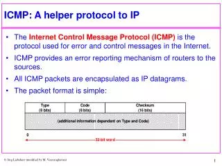
Download
1 / 38
380 likes | 550 Views
IP Architecture Overview. IP is a layered protocol, designed to facilitates the exchange of data between two computers. In the IP universe, the application is responsible for formatting data such that its peer(s) can understand it.

E N D
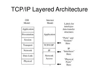
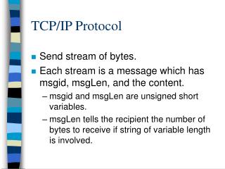
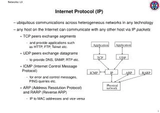
IP Architecture Overview • IP is a layered protocol, designed to facilitates the exchange of • data between two computers. • In the IP universe, the application is responsible for formatting • data such that its peer(s) can understand it. • Applications employ a Transport layer protocol that provides • the capability for multiple applications to be running on one • machine. • Each Optionally, a Transport layer protocol may provide • reliability services, or ordered delivery services. It may also • provide a checksum over the Application-layer data, so that • correct reception of unaltered data may be verified.
IP Architecture Overview Continues • In the IP stack, the transport layer offers two very common choices: • (1) The Transmission Control Protocol(TCP), which is • a reliable transport protocol. • (2) The User datagram Protocol(UDP), which is a • more basic protocol that provides only multiple • applications “demultiplexing”. • IP carries TCP “segments” or UDP “datagrams”
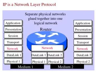
How do IP Routers communicate with each other • When IP entities need to communicate, they do so by employing any • number of lower-layer “sub-network” technologies. • There are either LAN sub-networks (e. g., Ethernet, Token Ring, etc.) • or WAN sub-networks (e. g., X.25 “clouds”, Frame Relay “clouds”, • ATM “clouds”, Switched Multimegabit Data Service (SMDS), etc.). • Routers are used to interconnect the various media “clouds”. • Each of these sub-networks has its own internal addressing format • and framing format. • Some sub-networks technologies employ both header and trailer • fields, and some encapsulate IP with only a header.
Subnetwork Layer Header DA SA T IP Packet IP IPX NetBEUI ? ? ? Sub-network Layer • The sub-network layer demultiplexing feature allows multiple protocol • stacks to share a common sub-network medium, or more importantly, • for multiple protocol stacks to be active on the same machine at the • same time. • Think of your PC-- you probably have Microsoft “NetBEUI”, Novell • Internetwork Packet eXchange (IPX), and IP all active. • Whether a PC, Mac, or Unix workstation is being used, all the active • protocol stacks share the same Network Interface Card (NIC) sub-net. • Address, so when the NIC receives a frame, it is clearly for one of the • protocol stack… but which one? The protocol type field tells the driver • software which protocol stack should get the frame’s embedded packet
ICMP TCP UDP ? ? ? Internet Protocol SA DA Pr. HIGHER-LAYER DATA Internet Protocol Layer Header • Once the IP layer has taken delivery of the packet from the sub-network • layer, it must first verify that its locally-assigned address matches the • packet’s destination address. • The IP header’s “Protocol” field (Pr) is the indicator of which higher- • layer protocol should receive the data encased within the packet. • Remember, just because a higher-layer protocol is a client of IP, it is not • necessarily a Transport-layer protocol. In such cases, you might say that • an application, or an application-like entity is running directly over IP, • with no intervening Transport layer protocol.
FTP POP3 WWW SP DP Application Data TCP Header ? ? ? TCP
TCP Data Unit Format TCP Data Unit TCP Header Options and Padding Source Port Destination Port Checksum Sequence Number Acknowledgement Number Window Urgent Point
TCP Data Unit Format • Source Port (16 bits)-identifies source service access point(SAP), i.e,address of an application within the source node or host • Destination Port(16 bits)-identifies source service access point(SAP) • Sequence Number(32 bits)-number of the first data byte in information PDU • Acknowledgment Number(32 bits)-sequence number of next byte expected by TCP entity • Cntrl = Control Bits(6 bits)-bits are set to indicate urgency,request rest,synchronize sequence numbers, and end of datastream
R=Reserved (6 bits)-reserved for future uses • Window(16 bits) –for flow control,number of bytes that receive port will accept before acknowledgment • Checksum (16 bits)-see text for explanation • Urgent Pointer(16 bits)-indicates sequence number of byte following urgent data • Options (variable)-requests specific receive buffer size,and other services • Padding(variable)-ensures that Header is a multiple of 4 octets long
IP Data Unit Format IP DATAGRAM IP Header Offset Options and Padding Destination Address Service Total Length Protocol Header Checksum Identification Life Source Address Flag
IP Data Unit Format • V=version (4 bits)-identifies version of IP in use • HL=Header Length(4 bits)-specifies length of IP Header in multiples of 4 octets • Service=Type of Service(8 bits)-Specifies parameters such as desired reliability and throughput • Total Length(16 bits)-identifies length of datagram (or current fragment);maximum length 65 535 bits • Identification(16 bits)-sequence number • Flag(3 bits) –permit,or prohibit,fragmentation of datagram • Offset(13 bits)-I.e, fragment offset;indicates • where in PDU this fragment belongs
Life=Time to Live(8 bits)-measured in gateway hops;ensures fragment does not loop indefinitely • Protocol(8 bits)-identifies next-level protocol to receive data at destination • Header Checksum(16 bits)-performs error check on Header • Source Address(32 bits) • Destination Address(32 bits) • Options (Variable)-requests specific routing,handling,and other services • Padding(variable)-ensures that Header is a multiple of 4 octets long
The Physical Layer Packet Packet Virtual Bit Pipe DLC DLC Physical interface module on each side of the comm. channel Frames Frames RS-232-C Or X.21 RS-232-C Or X.21 Modem (DCE) Modem (DCE) Interface Wired Comm. Channel Interface Wired Request to send Clear signal Ready signal
Provides a virtual link for transmitting a sequence of bits between any pair of nodes joined by a physical communication channel. Such a virtual link is called a “Virtual Bit Pipe” • To achieve this function, there is a physical interface module on each side of the communication channel whose function is to map the incoming bits from the DLC layer into signals appropriate for the channel, and at the receiving end, to map the signals back to bits
The physical interface module that performs these mapping functions is called “a modem” (digital data modulator and demodulator). • How to deliver a string of bits from the DLC module to the modem is an interface issue. • The RS-232-C interface standard provides the interface between the DLC module (DTE) and the modem (DCE) by providing a separate wire between the two modules for each type. • RS-232-C is also referred to as standard for the serial port of computers. This standard is for low-bit-rate (up to 38kb/s) and short distance (< 30m) transmission
Serial transmission proceeds one character at a time. The computer encode each character into seven bits (ASCII), and add up one bit (parity bit) for error detection, so each character is represented by an 8-bit string. • Successive characters are separated by some time interval. • A serial link is used to attach a computer to a Modem. • In that sense RS-232-C standard is considered Asynchronous transmission standard between two computers.
Synchronous Data Link Control • In 1970 a synchronous transmission standard was introduced to increase the transmission rate and distance, known as SDLC (Synchronous Data Link Control). • The main idea of SDLC is to avoid the time wasted by RS-232-C caused by gaps between successive characters. This is done as follows: SDLC group many data bits (string) into packets, could be fixed length or variable length
H DATA CRC SDLC SDLC Packet Synchronous Data Link Control Cont… • SDLC uses an error detection code called the Cyclic Redundancy Check (CRC), that is more efficient and more powerful than the single parity bit of RS-232-C
IP Addresses • Unique, 32 bit (4 byte) identifiers for each interface • IP Addresses are hierarchical. They ate made of several part. • IP Addresses consist of two parts, a Network part and a Host part • The network part identifies the physical network to which the host is attached, • The Host part identifies each host uniquely on that particular network. • Class A: 126 networks with 16 million hosts each • Class B: 16382 networks with 64000 hosts each • Class C: 2 million networks with 254 hosts each • Dotted decimal notation: 0.0.0.0 – 255.255.255.255
H1 Internet Service Provider H H FDD Net # 1 R1 R2 PrivateLine Ethernet Net # 2 H5 H6 H7 Ethernet Net # 3 H2 H3 H4
Classful/Classless IP Addressing Two-Level Classful Hierarchy Network-Prefix Host-Number Three-Level Subnet Hierarchy Network-Prefix Subnet-Number Host-Number • The network number was always either 8, 16, or 24 bits long, with the host-number field being 24, 16, or 8 bits long, respectively. • The subnet-number field may be from 1 to (h-2) bits long, where ‘h’ is the length of the original host-number field. • The ultimate constraint is that n+s+h=32, where n, s, and h are the lengths of the network-number, subnet-number, and host-number fields, respectively.
Datagram Forwarding in IP • Every IP datagram contains the IP address of the destination • The “network part” of an IP address uniquely identifies a single physical network that is part of the larger internet • All hosts and routers that share the same network part of their address are connected to the same physical network and can communicate with each other by sending frames over that network • Every physical network that is part of the internet has at least one router that, by definition, is also connected to at least one other physical network;this router can exchange packets with hosts or routers on either network.
A datagram is sent from source host to destination host possibly passing through many routers • Any node (host or router), first tries to established whether it is connected to the same physical network as the destination. • It compares the network part of the destination address with the network part of the address of each of its network interfaces. • If a match occurs, that means the destination lies on the same physical network as the interface and the packet can be directly delivered over that network
If the node is not connected to the same physical network as the destination node • It needs to send the datagram to a router (it chooses the best router to get the datagram closer to destination). • The chosen router is known as the next-hop router. • Router finds the correct next-hop by consulting its forwarding table. • Forwarding table is a list of <destination, next-hop> pairs. • Normally, there is a default router in case of not finding any router match to send the datagram that are destined to outside the physical network of the host.
Address Resolution Protocol (ARP) IP packets contain IP addresses, but the physical interface hardware on the host or routers to which you want to send the datagram only understands the physical addressing scheme of that particular network.
C A: Host on Bus 1 B: Host on Bus 2 C: Router connecting Bus 1 and Bus 2 A Bus 1 a1 c1 B Bus 2 c2 b2 a1 c1, IP A B, TCP TCP Header + Data c2 b2, IP A B, TCP TCP Header + Data Ethernet Header IP Header Ethernet Header IP Header
Subnets • Internally split networks (a single network to the outer world) • Split the host address portion to • Subnets and host (i.e. smaller # of hosts) • Subnet masks
Subnet and IP Routing • IP Protocol Routing • Router has entries of the forms .. • (network_address, 0) -> for outside networks • (this_network, host) -> for hosts on the local networks • When a packet arrives destination address is looked up • Default route if the address is not present • Subnetting requires a small change • (this_network, subnet, host) • Subnet mask is ANDed with the destination address • Yields the network address that should be in the tables
Subnetting • Smaller groups of hosts in a “network” • May be defined recursively • The subnet structure is only visible to the higher network • Subnet mask allows the definition of subnet
By providing a structured way to deploy hierarchical addressing, subnetting made it possible to “hide” the internal structure of networks from the worldwide Internet. • This makes sense. After all, no one needs to know if you have 4, 7, or 17 subnets of your network number, or what they are; as long as the outsiders can reach your network number, they can reasonably expect to be able to reach whatever subnets you have defined within your network number.
By providing a structured way to deploy hierarchical addressing, subnetting made it possible to “hide” the internal structure of networks from the worldwide Internet. • This makes sense. After all, no one needs to know if you have 4, 7, or 17 subnets of your network number, or what they are; as long as the outsiders can reach your network number, they can reasonably expect to be able to reach whatever subnets you have defined within your network number.
The route from the Internet to any subnet of a given IP address is the same, no matter which subnet the destination host is on. • This is because all subnets of a given network number use the same network-prefix but different subnet-numbers. • The routers within the private organization need to differentiate between the individual subnets, but as far as the Internet routers are concerned, all of the subnets in the organization are collected into a single routing table entry and are generally reachable via the same router—the one that advertised the network number in the first place!
Subnet Example Network-Prefix Extended-Network-Prefix 27 Bits An organization has been assigned the network number 193.1.1.0/24 and it needs to define six subnets. The largest subnet is required to support 25 hosts. Subnet-Number Bits Host-Number Bits 193.1.1.0/24 = 11000001.00000001.00000001.00000000 255.255.255.224 = 11111111.11111111.11111111.11100000
Defining Each of the Subnet Numbers Base Net = 11000001.00000001.00000001.00000000 = 193.1.1.0/24 Subnet #0 = 11000001.00000001.00000001.00000000 = 193.1.1.0/27 Subnet #1 = 11000001.00000001.00000001.00100000 = 193.1.1.32/27 Subnet #2 = 11000001.00000001.00000001.01000000 = 193.1.1.64/27 … … Subnet #7 = 11000001.00000001.00000001.11100000 = 193.1.1.224/27
Defining Host Addresses for Each Subnet Subnet #2 = 11000001.00000001.00000001.01000000 = 193.1.1.64/27 Host #1 = 11000001.00000001.00000001.01000001 = 193.1.1.65/27 Host #2 = 11000001.00000001.00000001.01000010 = 193.1.1.66/27 … … Host #30 = 11000001.00000001.00000001.01011110 = 193.1.1.94/27