Download
1 / 37
370 likes | 512 Views
This course covers the essentials of LabVIEW programming, focusing on virtual instruments, data flow, and the use of graphical structures like for loops, while loops, and case structures. Learn about arrays, clusters, graphs, and advanced concepts such as state machines and SubVIs. Explore data acquisition techniques, signal conditioning, and measurement systems for accurate readings. Understand the intricacies of differential and single-ended measurements, and their impact on noise rejection. Ideal for anyone looking to delve deep into the practical applications of LabVIEW for engineering and data analysis.

E N D
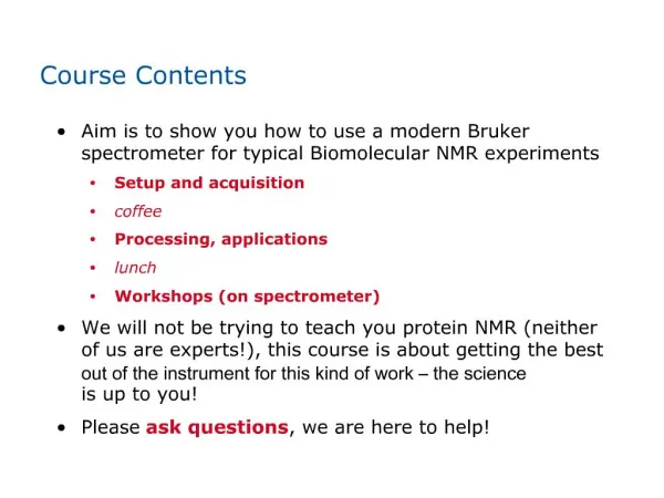
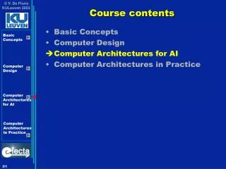
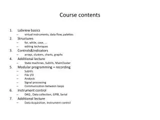
Course contents • Labview basics • virtual instruments, data flow, palettes • Structures • for, while, case, ... • editing techniques • Controls&Indicators • arrays, clusters, charts, graphs • Additional lecture • State machines, SubVIs, MainCluster • Modular programming + recording • SubVIs • File I/O • Analysis • Signal processing • Communication between loops • Instrument control • DAQ , Data collection, GPIB, Serial • Additional lecture • Data Acquisition, Instrument control
Most common signal conditioning • Amplification
Signal Sources • Grounded Signal • referenced to system ground (earth, building ground) • example: devices that plug into building ground through wall outlets (e.g. signal generator) • be aware of ground loops: Two independently grounded signal sources are generally not at the same potential
Signal Sources • Floating signal • not referenced to any common ground • for example batteries, thermocouples
Measurement systems • Differential measurement • measuring with respect to floating ground • neither of the inputs tied to fixed reference (building ground)
Measurement system • Referenced single-ended • measurement with respect to building ground
Measurement system • Nonreferenced single-ended • all measurement with respect to a common reference
What system to use? • In general, differential measurement system is preferable • Differential measurement rejects ground loops and noise from the environment • Single-ended measurements allow twice as many channels as differential • Use single-ended only if you have all of the following: • high-level signals (normally, greater than 1V, so that the induced errors are lower than the required accuracy) • short or properly-shielded cabling (normally, less than 3 m) • all signals can share commmon reference signal at the source • Do not use referenced single-ended connections with ground-referenced signal sources (ground loops!)
What system to use? • The noise rejection with non-referenced single-ended mode is better than referenced single-ended • Differential is better than non-referenced single-ended mode (AISENSE connection is shared with all channels)
Connections • See the user manuals for more information • e.g. USB-6210 http://www.ni.com/pdf/manuals/371931f.pdf
Differential • Referenced single-ended • Non-referenced single-ended
Multichannel scanning considerations • Multiplexer switches from one AI channel to the next • Instrumentation amplifier has to settle to the new input range • Settling time: time it takes the amplifier to amplify the input signal to the desired accuracy before it is sampled
For fast settling times: • Use low impedance sources • accumulated charge in multiplexer capasitor leaks through from previous to the next channel when switching between channels (ghosting) • Carefully choose the scanning order • avoid switching from large to small input range • scan grounded channel between signal channels: improves settling time • even with the same input range selected, if you know the expected signal levels, group the similar expected ranges together in your scanning list • If it’s not necessary to switch between channels, scan for example 100 samples from the first channel and only then switch to second channel and scan 100 samples
For fast settling times: • Avoid scanning faster than necessary • more time to settle • example: You need to scan 10 channels over a period of 20 ms average the result. Even if scanning with 250 kS/s gives more samples and therefore improves the standard error of the mean, scanning with 125 kS/s gives more settling time and can in some cases give more accurate results.
Analog-to-Digital Converter (ADC) • Resolution – number of bits in your ADC • Example: 3-bit ADC divides the measurement range to 23 = 8 divisions With 16-bits you have 65536 divisions
Analog-to-Digital Converter (ADC) • Device Range • minimum and maximum analog signal levels the device can digitize
Analog-to-Digital Converter (ADC) • Code Width • smallest detectable change in the signal, i.e. resolution • for example: 16-bit resolution, range from -10 to +10V code width = 20 V/2^16 = 305 µV • Nominal resolution is worse due to the calibration method of the device
Sampling rate • How often A/D conversion takes place • Aliasing is a result of too low sampling rate • Nyquist theorem • sampling rate has to be at least twice the measured frequency to accurately represent the signal • Nyquist frequency = Sampling frequency/2
Sampling rate • Example: Sampling rate 100 S/s; signal at 25 Hz is measured correctly but signals at 70 Hz, 160 Hz and 510 Hz are aliased to 30 Hz, 40 Hz, and 10 Hz
Hardware vs Software timing • Timing source can be on hardware or on software • on hardware a clock on the device determines the timing • on software the program loop determines the timing • Hardware timing is more accurate and faster
Analog output • Digital-to-Analog conversion • generate analog signal from computer • Single point update • software timed generation • change the output value everytime the program calls the VI • Buffered analog output • hardware timed generation • upload a waveform to the device and set the update rate of the device to go through the points
Digital I/O • Two states: • high and low • Control digital or finite state devices • switches, LEDs • Program devices or communicate between devices • Example: Digital frequency generator takes 30-bit control word which defines the generated frequency – use digital output ports of a DAQ-device to generate this word
Wirings • USB-6008
Instrument Control • GPIB • Serial port • Image Acquisition • USB • Ethernet • Parallel port
GPIB • General Purpose Interface Bus (GPIB) • a.k.a HP-IB, IEEE 488 • GPIB is usually used in stand alone bench top instruments to control measurements and communicate data • supported by many instrument manufacturers • Digital, 24-conductor, 8-bit parallel communication interface • 16 signal lines, 8 ground return lines • 8 data lines: data sended in bytes • 3 handshake lines: control the transfer of messages • 5 interface management lines • Data transfer rate typically 1Mbyte/s • IEEE 488.1 and 488.2 define standards for GPIB
GPIB • GPIB configurations • you can have multiple devices connected to the same computer • Device groups • Talker • Listener • Controller
GPIB • GPIB has one (active) controller that controls the bus • usually this is the computer • it connects the talkers to listeners • Physical requirements • maximum separation between two devices 4 m (for high-speed use only 1 m) • maximum total cable length 20 m • maximum of 15 devices on a bus (at least 2/3 turned on)
Serial Port Communication • Communicate with only one device • No need to buy additional hardware like with GPIB (although modern computers don’t always have RS-232 port anymore) • Send data one bit at a time • you can have long distance between devices • data transfer rate is low
Serial Port Communication • Before communication you need to define • baud rate • number of data bits for a character • parity bit • number of stop bits • Two voltage stages • positive > 3V • negative < -3V • area between +3V and -3V is designed to absorb noise
Instrument Drivers • Software to control a particular instrument • VISA – Virtual Instrument Software Architecture • library for controlling GPIB, serial, Ethernet, USB, or VXI instruments • Example: Agilent 34401 Digital Multimeter
Instrument Drivers • Download from ni.com • Help >> Find Instrument Drivers • requires login
Instrument Drivers • After installation the drivers can be found from functions palette
Links • User manual for M-series USB-621x • http://www.ni.com/pdf/manuals/371931f.pdf • Labview data-aquisition manual • www.ni.com/pdf/manuals/320997e.pdf • Labview Measurement Manual • http://www.ni.com/pdf/manuals/322661b.pdf • Understanding Instrument Specifications • http://zone.ni.com/devzone/cda/tut/p/id/4439#2 • Ghosting in multichannel sampling • http://digital.ni.com/public.nsf/allkb/73CB0FB296814E2286256FFD00028DDF?OpenDocument