MIS 335 - Database Systems Entity-Relationship Model
MIS 335 - Database Systems Entity-Relationship Model. Ahmet Onur Durahim. http://www.mis.boun.edu.tr/durahim/. Learning Objectives. Database Design Main concepts in the ER model? ER Diagrams. Database Design and ER Diagrams.

MIS 335 - Database Systems Entity-Relationship Model
E N D
Presentation Transcript
MIS 335 - Database SystemsEntity-Relationship Model Ahmet Onur Durahim http://www.mis.boun.edu.tr/durahim/
Learning Objectives • Database Design • Main concepts in the ER model? • ER Diagrams
Database Design and ER Diagrams • Requirements Analysis: find out what the users want from the database • What data is to be stored in the DB • What applications must be built on top of it • What operations are most frequent and subject to performance requirements • Conceptual Database Design:create a simple description of the data that closely matches how users and developers think of the data • A high-level (semantic) description of data to be stored in the DB along with the constraints known to hold over this data • Carried out using the ER Model • Logical Database Design: choose DBMS to implement conceptual database design • Convert conceptual DB design (ER schema) into a DB schema in the data model of the chosen DBMS (relational DB schema)
DB Design • Schema Refinement • Analyze the collection of relations in relational DB schema to identify potential problems and refine it (- Normalization of the relations) • Physical DB Design • Consider expected workloads to refine for meeting the desired performance criteria • Building indexes on tables • Clustering some tables • Redesign of parts of the DB schema • Application and Security Design • Identify entities (users, departments) and relevant roles of each entity • Enforce access rules: For each role, identify the parts of the DB that must be accessible and must not be accessible
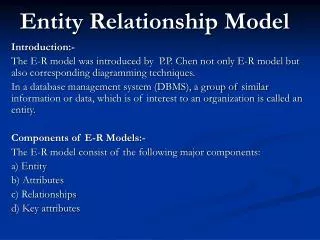
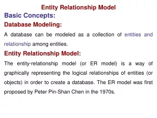
Entity-Relationship Model • Before developing your database application, you need to • Collect the requirements • Build a conceptual database design • ER Model: used to describe the data involved in an enterprise in terms of objects and relationships • Widely accepted standard for initial (conceptual) database design
Entity-Relationship Model • Conceptual DB design: • What information about these entities and relationships should we store in the database? • What are the integrity constraints or business rules that hold? • A database `schema’ in the ER Model can be represented pictorially • ER diagrams • Can map an ER diagram into a relational schema
name cost pname age ssn lot Policy Dependents Employees Entity-Relationship Diagram
Key Concepts of ER Model • Entities • An object that is capable of independent existence and can be uniquely identified (can be distinguished from other objects) • An entity is described using a set of attributes Item Employee Student ssn type sid
Key Concepts of ER Model • Entity set • A collection of similar entities • share the same set of properties/attributes • Reflects the level of detail at to represent information about entities Students Alp Onur Zubeyde Esra Arzu Ahmet
Key Concepts of ER Model • Entity set may overlap • Any example? Students Employees Alp Onur Mert Zubeyde Esra Emrecan Arzu Ahmet Mehmet
Key Concepts of ER Model • Each entity sets has attributes • Each attribute has a domain • Domain: set of permitted values • name attribute – (set of 20-character string) • age attribute – (set of integers between 0-150) • Each entity set has a key • minimal set of attributes whose values uniquely identify an entity in the set • denoted by underlining the attribute name in the ER-diagram Employee ssn address name
Key Concepts of ER Model • Relationships • Association (relation) among two or more entities • Ahmet is enrolled in MIS335 • Relationship sets • A collection of similar relationships • Share the same properties Works_In Enrolled
Key Concepts of ER Model • Relationships also has attributes • Descriptive attributes: used to record the information about the relationship • Ahmet Works_In University since 2014 Employee Works_In ssn address name since
ER Model cname Enrolled sid Student Course cid name semester Rectangles : Entity sets Diamonds : Relationship Sets Ellipses/Oval : Attributes
ER Model • Degree of a relationship set is the number of entity sets that participate in a relationship • Binary relationship sets involve two entity sets cname Enrolled sid Student Course name semester cid
ER Model • Ternary relationship sets involve three entity sets Locations address capacity Works_In Employee Departments ssn name budget did since dname
ER Model • The set of entities that participate in a relationship set may belong to the same entity set • Each entity plays a different role in such a relationship Employees ssn name Employees subordinate supervisor Reports_To Reports_To => Unary relationship
ER Model • The set of entities that participate in a relationship set may belong to the same entity set • Each entity plays a different role in such a relationship Student sid name Students tutee tutor Helps
Cardinality Mappings • One-to-One (1-1) • One occurrence of an entity relates to only one occurrence in another entity • rarely exists in practice • consider combining them into one entity • Example: an employee is allocated a company car, which can only be driven by that employee • One-to-Many (1-M) / Many-to-One (M-1) • One occurrence in an entity relates to many occurrences in another entity • Example: an employee works in one department but a department has many employees.
Cardinality Mappings • Many-to-Many (M-N) • Many occurrences in an entity relate to many occurrences in another entity • The normalisation process would prevent any such relationships • Rarely exist • They occur because an entity has been missed. • Example: an employee may work on several projects at the same time and a project has a team of many employees. • In the normalisation process this many-to-many is resolved by the entity Project Team.
Cardinality Mappings 1-to-1 1-to-Many Many-to-1 Many-to-Many
ER Model – Key Constraints Works_In Departments Employees dname did ssn name since since An employee can Work In multiple departments and a department can have multiple employees. What is the type of this relationship? Many-to-Many
ER Model – Key Constraints Manages Departments Employees dname did ssn name since since An employee can Manage multiple departments, but a department can be managed by only one employee (Manager) What is the type of this relationship? This is called a key constraint (the restriction that each department has at most one manager) denoted by an arrow 1-to-Many
An Instance of the Manages Relationship Set Department with did = ‘51’ violates thekey constraint of the Manages relationship Instance of Manages relationship that satisfies the key constraint of the Manages relationship
Participation Constraints • If every department is required to have a manager, this requirement is a participation constraint • The participation of the entity set Departments in the relationship set Manages is total • The participation of the entity set Employees in the relationship set Manages is partial • Since not every employee gets to manage a department • Total participation constraint of an Entity set in a relationship set is indicated by connecting them by thick line Manages Departments Employees dname did ssn name since since
Participation Constraints • If each employee works in at least one department, and if each department has at least one employee • Total or Partial Participation of Employees & Departments entities since Works_In Manages Departments Employees dname did ssn name since since
Class/ISA (“is a”) Hierarchies ssn • Classify entities into subclasses • Every entity in a subclass also belongs to superclass (Employees) • The attributes for the entity set Employees are inherited by the entity set Hourly_Emps • Hourly_EmpsISA Employees name Employees ISA • Reasons for using ISA: • To add descriptive attributes specific to a subclass. • To identify entities that participate in a relationship Hourly_Emps Contract_Emps hours_worked hourly_wages contractid
Class/ISA (“is a”) Hierarchies ssn • Specialization: process of identifying subsets of an entity set (Employees) that share some distinguishing characteristic • Employees is specialized into subclasses • Generalization: process of identifying some common characteristics of a collection of entity sets and creating a new entity set that contains entities possessing these common characteristics • Hourly_Emps and Contract_Emps are generalized by Employees name Employees ISA Hourly_Emps Contract_Emps hours_worked hourly_wages contractid
Class/ISA (“is a”) Hierarchies ssn • Overlap Constraints: determine whether two subclasses are allowed to contain the same entity • Can Ahmet belong to both Contract_Emps entity and Hourly_Emps? • Covering Constraints:determine whether the entities in the subclasses collectively include all entities in the superclass • Does every Employees entity have to belong to one of Hourly_Emps and Contract_Emps? name Employees ISA Hourly_Emps Contract_Emps hours_worked hourly_wages contractid
Weak Entities • Weak Entity: Entity set that does not include a key • A weak entity can be identified uniquely only by considering the primary key of another entity (called identifying owner) • Set of attributes of a weak entity set that uniquely identify a weak entity for a given owner entity => partial key • A weak entity set is denoted by a rectangle with thick lines Policy Dependents Dependents Employees pname ssn name cost age
Weak Entities • A weak entity can be identified uniquely only by considering the primary key of another entity (called identifying owner) • A weak entity set is denoted by a rectangle with thick lines • The relationship between a week entity and the owner entity is denoted by a diamond with thick lines Policy Policy Dependents Dependents Employees pname ssn name cost age
Weak Entities • A weak entity can be identified uniquely only by considering the primary key of another entity (called identifying owner) • What can you say about the constraints on the identifying relationship? (i.e., participation and key constraints) Policy Policy Dependents Dependents Employees pname ssn name cost age
Weak Entities • What can you say about the constraints on the identifying relationship? (i.e., participation and key constraints) • Owner entity set and weak entity set must participate in a one-to-many relationship set (one owner, many weak entities) • Weak entity set must have total participation in this identifying relationship set Policy Policy Dependents Dependents Employees pname ssn name cost age
ssn Aggregation name Employees • Used to indicate that a relationship set (denoted by a dashed box) participates in another relationship set • Allows us to treat a relationship set as an entity set for purposes of participation in other relationships Monitors until Sponsors Projects Departments started_on did dname pid since pbudget budget • Aggregation vs. Ternary relationship: • Monitors is a distinct relationship, with a descriptive attribute • Also, can say that each sponsorship is monitored by at most one employee
Conceptual Design Using the ER Model • Design choices: • Should a concept be modeled as an entity or an attribute? • Should a concept be modeled as an entity or a relationship? • Identifying relationships: Binary or ternary? Aggregation? • Constraints in the ER Model: • A lot of data semantics can (and should) be captured • But some constraints cannot be captured in ER diagrams
Entity vs. Attribute • Should addressbe an attribute of Employees or an entity (connected to Employees by a relationship)? • Depends upon the use we want to make of address information, and the semantics of the data: • If only one address is to be recorded per employee • Use attribute ‘address’ • If we have several addresses per employee • addressmust be an entity (since attributes cannot be set-valued) • If we want to capture the structure (break down address into country, city, street, etc.) of an address • e.g., we want to retrieve employees in a given city • addressmust be modeled as an entity (since attribute values are atomic)
Entity vs. Attribute to from • Works_Indoes not allow an employee to work in a department for two or more periods • This possibility is ruled out by the ER diagram’s semantic, because relationship is uniquely identified by the participating entities (without reference to its descriptive attributes) • Similar to the problem of wanting to record several addresses for an employee • We want to record several values of the descriptive attributes for each instance of this relationship • Accomplished by introducing new entity set, Duration Works_In Employees Departments did ssn dname name budget Duration from to Works_In Employees Departments did ssn dname name budget
Entity vs. Relationship dbudget since Manages • ER diagram is OK if a manager gets a separate discretionary budget for each department • What if a manager gets a discretionary budget that covers all managed departments? • Redundancy: dbudgetstored for each dept managed by manager • Misleading: Suggests dbudget associated with department-mgr combination Employees Departments did ssn dname name budget name ssn Employees Manages Departments ISA did dname Managers since dbudget budget
Entity vs. Relationship dbudget since Manages • ER diagram is OK if a manager gets a separate discretionary budget for each department • What if a manager gets a discretionary budget that covers all managed departments? • Redundancy: dbudgetstored for each dept managed by manager • Misleading: Suggests dbudget associated with department-mgr combination Employees Departments did ssn dname name budget name ssn since Employees Manages Departments Redundancies are eliminated by Normalization technique ISA did dname Managers dbudget budget
Binary vs. Ternary Relationship name pname • Models the situation where; • An employee can own several policies • Each policy can be owned by several employees • Each dependent can be covered by several policies ssn age Covers Employees Dependents Policies policyid cost
Binary vs. Ternary Relationship name pname • If we have additional requirements; • A policy cannot be owned jointly by two or more employees • Every policy must be owned by some employee • Dependents is a weak entity, and uniquely identified by taking pname in conjunction with policyid of a policy entity • ER diagram is inaccurate ssn age Covers Employees Dependents Bad design Policies policyid cost name ssn pname age • What are the additional constraints in the 2nd diagram? Employees Dependents Purchaser Beneficiary Better design Policies policyid cost
Binary vs. Ternary Relationship (Contd.) • An example in the other direction: • A ternary relation Contracts relates entity sets Parts, Departments and Suppliers, and has descriptive attribute qty. • No combination of binary relationships is an adequate substitute: • S “can-supply” P, D “needs” P, and D “deals-with” S does not imply that D has agreed to buy P from S • How do we record qty?
Summary of Conceptual Design • Conceptual design follows requirements analysis • Yields a high-level description of data to be stored • ER model popular for conceptual design • Constructs are expressive, close to the way people think about their applications • Basic constructs • entities, relationships, and attributes (of entities and relationships) • Some additional constructs • weak entities, ISA hierarchies, and aggregation • Note: There are many variations on ER model
Summary of Conceptual Design • Several kinds of integrity constraints can be expressed in the ER model: • key constraints • participationconstraints • overlap/covering constraints for ISA hierarchies • Some foreign key constraintsare also implicit in the definition of a relationship set • Some constraints (notably, functional dependencies) cannot be expressed in the ER model • Constraintsplay an important role in determining the best database design for an enterprise
Summary of Conceptual Design • ER design is subjective • There are often many ways (alternatives) to model a given scenario • Common choices include: • Entity vs. attribute, Entity vs. relationship • Binary or n-aryrelationship • Whether or not to use ISA hierarchies / aggregation • To ensuring good database design: • Resulting relational schema should be analyzed and refined further • FD information and normalization techniques are especially useful
ER Modeling Question - 0 • Should explain the following terms: • entity, relationship, entity set, relationship set, • attribute, domain, • one-to-many relationship, many-to-many relationship, • participation constraint, overlap constraint, covering constraint, • weak entity set, aggregation, role indicator.
ER Modeling Example - 1 • A university database contains information about professors (identified by social security number, or SSN) and courses (identified by courseid) • Professors teach courses; each of the following situations concerns the Teaches relationship set. • For each situation, draw an ER diagram that describes it (assuming no further constraints hold)
ER Modeling Example - 1 • Professors can teach the same course in several semesters, and each offering must be recorded • Professors can teach the same course in several semesters, and only the most recent such offering needs to be recorded. (Assume this condition applies in all subsequent questions.) • Every professor must teach some course
ER Modeling Example - 1 • Every professor teaches exactly one course (no more, no less) • Every professor teaches exactly one course (no more, no less), and every course must be taught by some professor • Now suppose that certain courses can be taught by a team of professors jointly, but it is possible that no one professor in a team can teach the course. Model this situation, introducing additional entity sets and relationship sets if necessary