Download
1 / 14
140 likes | 304 Views
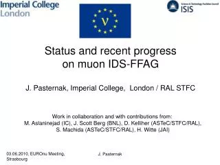
Status and recent progress on muon IDS-FFAG J. Pasternak, Imperial College, London / RAL STFC. Work in collaboration and with contributions from: M. Aslaninejad (IC), J. Scott Berg (BNL), D. Kelliher (ASTeC/STFC/RAL), S. Machida (ASTeC/STFC/RAL), H. Witte (JAI). Outline of the talk.

E N D
Status and recent progress on muon IDS-FFAG J. Pasternak, Imperial College, London / RAL STFC Work in collaboration and with contributions from: M. Aslaninejad (IC), J. Scott Berg (BNL), D. Kelliher (ASTeC/STFC/RAL), S. Machida (ASTeC/STFC/RAL), H. Witte (JAI) J. Pasternak
Outline of the talk • Current baseline IDS FFAG design and alternative • (J. Scott Berg, S. Machida). • Studies of injection/extraction for IDS muon FFAG • (D. Kelliher, J.P., M. Aslaninejad, H. Witte). • Injection/extraction hardware design studies • (M. Aslaninejad, H. Witte, J.P.). • Summary and future plans. J. Pasternak
Introduction • Non-scaling FFAG is preferred for muon acceleration from 12.6 to the final 25 GeV attheNeutrino Factory. Advantages include: • Allows very fast acceleration (~8-16 turns). • Large dynamic aperture due to linear magnets + high degree of symmetry • More turns than in RLA – more efficient use of rf • Quasi-isochronous – allows fixed frequency rf • Orbit excursion and hence magnet aperture smaller than in the case of a scaling FFAG • Principles of NS-FFAG will be soon tested during EMMA commissioning. J. Pasternak
Current NS-FFAG baseline • Lattice choice triplet with long drift: • due to longest drift injection/extraction • seems to be most feasible comparing • to other lattices • allows for symmetric injection/extraction, • good performance • but less cost-effective than the short drift • triplet, • lattice needs to be further studied and • optimised. • chromaticity correction can be added • in order to correct the final energy spread • due to ToF Scott’s lattice parameters. J. Pasternak
Alternative solution - Nonliner NS-FFAG, S. Machida Layout of FFAG with insertions J. Pasternak
Introduction to injection/extraction • Working assumptions: • Try to distribute kickers to reduce their strengths. • Apply mirror symmetric solution to reuse kickers for both signs of muons. Positive Muons Negative Muons F D F D F D F Septum Septum Kickers J. Pasternak
Injection/Extraction in the Long Drift Triplet, D. Kelliher Injection geometry Extraction geometry • Large beam excursion • near the septum requires • special magnets with • large aperture. • Those magnets may • introduce orbit and optics • distortions (correction can • be possible). J. Pasternak
Orbit shift due to extended fringe fields, J. P. m • There are 3 curves on the plot: • -orbit with the hard edge model, • - with the soft edge model, • - with shifted magnets Zoom to see the difference between hard edge and soft edge results with shifted magnets. This study suggest, that just by shifting the magnets we can correct the effect of special magnets on orbit distortion in the injection/extraction regions. GeV J. Pasternak
Preliminary study of IDS kickers (H.W., J.P.) • Due to the proton beam time structure, at least 3 independent Pulse Forming Networks • (PFNs) and switches are needed for every muon train. • Termination is very important to avoid reflections back to magnet (for injection). • Current is most likely to high for a single thyratron, but we can connect them • in paralell. PFN switch PS Kicker PFN switch Transmission line Termination PFN switch J. Pasternak
IDS Kicker Kicker geometry EM simulations, M. Aslaninejad. • Geometry • Aperture: 0.3x0.3 m2 • Yoke: 120 mm • Length: 2.4 m • Field: 100 mT • Current: 29 kA • Magnetic energy: 500 J • Inductance (single turn): 2.8 uH • Impedance matching • Add 5 plate capacitors (40 mm available) J. Pasternak
Pulses for 3 muon buch trains separated by 100 us. J. Pasternak
Recent progress on kicker circuit, H. Witte 3 Ohm PFN 1 Tfire=0 us PFN 2 Lmag PFN 3 PFN 4 1 Ohm Rterm PFN 5 Tfire=100 us PFN 6 The assumed impedance was changed: Each PFN: Z= 3 Ohms Voltage: 60 kV Peak current: 30 kA Peak current thyratron: 10 kA Kicker: subdivided into 3 smaller kickers Each kicker: Travelling wave, 20 sections PFN 7 Tfire=200 us PFN 8 PFN 9 J. Pasternak
Average current in Kicker 2 us 1.5 us 2 us J. Pasternak
Summary • Injection/extraction schemes in the NS-FFAG lattices • were evaluated. The triplet lattice with long drift was chosen as the baseline. • Alternative Nonlinear NS lattice with insertions and partial chromaticity • correction was proposed. • More beam dynamics studies are needed • (chromaticity correction, errors, insertion). • Substantial progress on the injection/extraction kicker design was achieved! • Work focuses on the design of the superconducting extraction septum! J. Pasternak