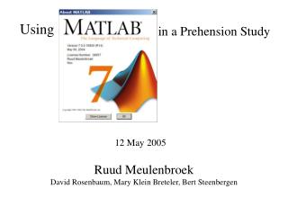
Using Mastan
Using Mastan. Next slide. Introduction. Mastan is an engineering analysis tool used to analyze how different structures will react under specific loading conditions.

Using Mastan
E N D
Presentation Transcript
Using Mastan Next slide
Introduction Mastan is an engineering analysis tool used to analyze how different structures will react under specific loading conditions. Because Mastan uses the Matlab engine to do its calculations, it can do a wide range of analyses that are cumbersome or impossible on paper. Last slide visited Previous slide
Outline • Structure Definition • Example problem: Truss • Example problem: Frame • Miscellaneous options
Before you begin, you must know: • Geometry: nodes and elements • Connections (fixed/pinned, frame/truss) • Fixities (physical restraints on the structure) • Sectional Properties • A: cross-sectional area of each beam • I: second moment of area • J: torsion constant • Material Properties • E: modulus of elasticity • : Poisson’s ratio • Yield stress Next slide: picture or specific example Next instruction slide
Definition: Nodes and Elements Elements (also called members) are the actual beams and columns your structure is made from. Nodes are the joints between elements. Nodes must be placed first, and then connected by elements in Mastan
Definition: Connections The kind of joints you are using is crucial to your structure. Use pins as joints for a truss, and fixed joints (such as welds) for a frame. It is usually not necessary to tell Mastan what kind of connections you are using until analysis time.
Definition: Fixities These are the physical restraints on the structure, for example, the way your structure is fixed to the ground.
Definition: Physical Properties(Properties dependent upon shape rather than material) • A: cross-sectional area of beam • I (second moment of area): I describes how difficult it is to spin the object in question about a certain axis. • J: the torsional constant, which describes how difficult it is to twist the object. (optional for Mastan)
Material Properties: (Properties dependent on material) • E: Young’s modulus, or modulus of elasticity: E is a measure of how much you have to pull on something to make it stretch a certain amount. • : Poisson’s ratio: the ratio of axial stretch to lateral shrink for different materials.
ƒy Stress Strain Material Properties, cont’d • Yield stress: Stress is force applied over a given area. Yield stress is that point where the ratio of the force applied on the object to its area has reached the point where the object will fail.
Working with Mastan In order to analyze a structure, you must input it into the program. The relevant components are: • Nodes • Elements • Connections • Sections (Define and Attach) • Materials (Define and Attach) • Fixities • Loads (also, Moments and Distributed Loads)
4m 4m 4m 4m 4m 4m 4m Example Problem: Truss Objectives: • Deflected shape diagram • Axial Force diagram • Node displacements • Reactions • Element results 200 kN 300 kN 500 kN 400 kN 300 kN
Example Problem: Truss (cont’d) This truss, is made of two kinds of elements. The vertical members are wide flange W203X60 beams (A=7550mm2, Izz=60.8*106 mm4, Iyy=20.4*106 mm4) made of Structural Steel (E=200GPa, max=250MPa. All other members are wide flange W203X36 beams (A=4570m2, Izz=34.5*106 mm4, Iyy=7.61*106 mm4) made of annealed stainless steel (18-8) (E=190GPa, max=250MPa)
Adding Nodes (rectangular frame) • Go to Geometry/Define Frame and enter the number and width of the bays, the number and height of the stories, and (for 3D frames) the number and depth of the frames in each box respectively. Hit “Apply.” • You may need to move some of the nodes; to do so, go to Geometry/Move Node, select the node(s) you need to move by clicking on them, and enter the amount you want to move them (NOT their new coordinates) in the boxes at the bottom of the screen.
Mastan will work with any consistent set of units. We are using kN-mm-MPa.
Adding Nodes (manual layouts) If you are building anything other than a rectangular frame, you will need to enter each node manually. Go to Geometry/Define Node, and enter the (x,y,z) coordinates of each node in the boxes at the bottom of the screen, pressing “Apply” after each one.
Adding Elements Go to Geometry/Define Element. For each element, click on each of its end nodes to select them, and press “Apply.”
Add enough elements to connect all nodes as shown, including this last one.
Subdividing Elements If necessary, it is possible to subdivide elements into as many equally-sized pieces as desired. This option is found under the Geometry menu. As an added note, the Geometry menu gives the options to move or duplicate nodes and reorient elements, should the need arise.
Notes on Material and Sectional Property Sets • Note that elements do not become deselected after you attach the property set to them – you must deselect them yourself. • If you attach a second section or material property set to an element, it will replace the first. • Properties/”Remove Section” or ”Remove Material” deletes the section or material definition, rather than giving you the option to unattach it from one or more elements • As you attach a section or material property set to an element, that element goes from being represented by a dotted line to a dashed one, and then to a solid line once both property sets are attached
Defining Sectional Properties • Go to Properties/Define Section, and enter your values of A and I (use Izz if the element is expected to bend around the z-axis, Iyy if the bending will occur around the y-axis) in the boxes at the bottom of the screen, then click “Apply.” • If your structure will be made up of parts with different cross sections, continue to define sections for each one.
Defined the first section, hit “Apply” to define the second section.
Applying Sectional Properties to Individual Elements • Go to Properties/Attach Section • Select all of the elements that have the first cross section • Make sure the first section is selected in the boxes at the bottom of the screen • Hit “Apply” • Continue in this manner until all of your elements have sectional property sets attached
Attach Section 2 to vertical members after attaching Section 1 to all others
Defining Material Properties • Go to Properties /Define Material, and enter your value of E in the box at the bottom of the screen. • Also enter if you have it. Yield stress will be represented as Fy, which can be left as infinity. • Hit “Apply” and continue in this manner until you have defined all of the materials that you will be using.
Hit “Apply” to define Material 2, after defining Material 1.
Applying Material Properties to Individual Elements • Go to Properties/Attach Material • Select all of the elements that will be made from that material • Make sure the first section is selected in the boxes at the bottom of the screen • Hit “Apply.” • Continue in this manner until all of your elements have material property sets attached.
Attach Material 2 to vertical members after attaching Material 1 to all others.
Defining Conditions Next, define the conditions under which the structure will be placed, including: • Fixities • Loads • Moments • Distributed Loads
Defining Fixities • Go to Conditions/Fixities. • Select one of the nodes that will be attached to the ground • Check the boxes that correspond to the degrees of freedom that will be restrained. For example, if your structure is simply supported (meaning one end is held in place with a pin joint, the other using a roller along the x-axis), you will check x, y, and z motion (but no rotation boxes) for the first joint, but only y and z motion (again, no rotation) for the second joint. • Hit “Apply.”
The structure is simply supported (pin on left, roller on right)
Applying Point Loads and Moments • Under the Conditions menu, select the kind of effect you want to apply. • Select the node to which you will apply it. • Enter the x, y, and z components of the effect into the boxes at the bottom of the screen. • Hit “Apply.”
Example Problem: Frame Objectives: • Shear force diagram • Moment diagram • Element results
Applying Distributed Loads • Under Conditions menu, select “Distributed Loads” • Select the element(s) to which you want to apply the load • Enter the x, y, and z components into the boxes at the bottom of the screen • Hit “Apply”
Analysis • Mastan is capable of many different types of analyses • The data resultant from these analyses can be displayed as • Diagrams, or • Numeric results
Definition: Elastic and Inelastic Behavior Elastic behavior: When a loaded object is stretched and then the load is removed, the object returns to its original size and shape, much like an elastic band would. Inelastic behavior: When the load permanently deforms the object, even after it is removed.
1st and 2nd Order Elastic Analyses • Go to the Analysis menu and pick the type of analysis you would like to perform. • Choose Space frame, space truss, plane frame (x,y), or plane truss (x,y), depending on how your structure is put together and supported.
Diagrams • Diagrams can be made by selecting the desired diagram from under the Results/Diagrams menu from: • Deflected shape • Axial force • Shear, Y and Z • Torque • Moment, Y and Z
Numeric Results • Pure numeric results can be found by selecting the node or element for which the results are needed, after choosing from the Results menu: • Node Displacements • Node Reactions • Element Results