Download
1 / 60
600 likes | 752 Views
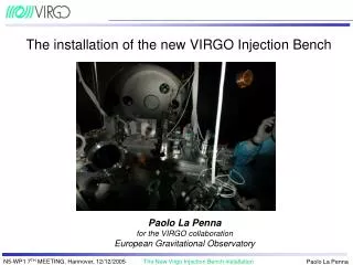
The installation of the n ew VIRGO Injection Bench. Paolo La Penna for the VIRGO collaboration European Gravitational Observatory. Recombined configuration: first half of 2004. IB. Recycled interferometer: July 2004. IB. PR reflection inside IMC: frequency noise. Black: PR misaligned

E N D
The installation of the new VIRGO Injection Bench Paolo La Penna for the VIRGO collaboration European Gravitational Observatory
PR reflection inside IMC: frequency noise Black: PR misaligned Red: PR aligned
PR reflection scattering inside IMC MC scattering (10 ppm) IMC PR Cavity effect (10% fringes)
The old PR was made by two parts: a curved one inside an external cylindrical glass mass (it was a lens, part of the telescope for collimating inside the ITF) The curved part was fixed to the cylindrical by means of a steel ring and pression screws; There was evidence of mechanical resonances (drifting in time): problems in locking acquisition and in the future Frequency Stabilization: need of a monolitic mirror Decided to make it plane (get rid of transverse movements of the beam induced by the suspension displacements) Plane Power Recycling mirror
IMC and RFC alignment ABP OFF 10% ABP dismounted The beam was atomatically aligned on the RFC (fixed below the IB) with ABP The IMC was partly automatically aligned (feedback only on the MC mirror The RFC was more stable than IMC: the AA of the RFC worked quite well the poor AA of the IMC couldn’t correct the drifts
PR reflection: Input Beam Attenuation (temporary solution) IMC 10% M6 From the laser To the interferometer 700 mW (10% of the full power) Reference Cavity
Simulations on a lock acquisition technique developed following the LIGO experience Locking trials with this baseline technique failed (first half of July) Beam attenuation installed (summer) The PR feedback inside the IMC (mid of 2004)
HR M6 vs attenuated M6 HR M6 (Same y-scale) R=10% M6 Hz Hz
Restart of the locking trials with the baseline technique (21st September) Establishement of theVariable Finesse lock acquisition technique (October) PR locking acquisition after one month (end of October 2004) CONFIRMATION OF THE BACKSCATTERING PROBLEM NEED OF AN OPTICAL ISOLATOR (FARADAY) The PR feedback inside the IMC (end of 2004)
The reflection of the light inside the Input Mode Cleaner increased the frequency noise, thus making it impossible to lock the recycling cavity The use of a Faraday isolator was necessary There was no way to accomodate a Faraday isolator and respective telescope on the old IB: the bench had to be replaced In addition to this: It was decided to replace the curved PR with a plane PR (less coupling with the transverse PR displacement): a short (parabolic) telescope on the IB was necessary It was decided to change the automatic alignment system of the injection system: separate alignment of the Input Mode Cleaner and Reference Cavity Resume: why to build a new Injection Bench
The aforementioned problems were individuated in many data takings (C1-C4) The mechanical design of the bench was performed using essentially Autocad and Ansys The optical simulation of the bench was performed using mainly Zemax (simulation of optical aberrations and stray light), and by Optocad The Faraday isolator was tested in Nice with the 20W laser The new IB was mounted and prealigned in Class 10 room (after old IB dismounting) Once prealigned it has been inserted into the tower How did we proceed
Upper part layout Optocad drawing Autocad drawing
Lower (RFC) part layout Optocad drawing Autocad drawing
ANSYS model Marionette Reference Cavity
ANSYS simulation 30 40 50 60 70 80 90 Probably Dihedron Legs (measured in september 2005) Susp. Wire couplers Uy Tx Tz
Plane PR: Beam simulation with spherical mirrors Input mirrors End mirrors
Plane PR: Beam simulation with parabolic mirrors Input mirrors End mirrors
Plane PR: (new) 6 parabolic off-axis telescope • With plane PR: a big magnification is needed, • the telescope has to be short (about 700 mm) • Parabolic mirrors are needed • The computed curvature radius are not off-shelf: custom mirrors (Optical Surface) IMC: waist 4.9 mm Condensing telescope FI: waist 2.65 mm M5: f= 75 mm M6: f = 600 mm Ø 10 cm to PR: waist=20 mm d= 675 mm
Parabolic telescope mechanical mount Two open loop picomotors Three closed loop picomotors X and Z closed loop translators Mounts designed by ourselves and Machined by a workshop close to Virgo Mounting commercial actuators
Starting conditions: misaligned, mismatched AUTOCOLLIMATOR
1st autocollimator alignment AUTOCOLLIMATOR REF. MIRROR AUTOCOLLIMATOR
2nd autocollimator alignment AUTOCOLLIMATOR AUTOCOLLIMATOR REF. MIRROR
Autocollimators aligned AUTOCOLLIMATOR AUTOCOLLIMATOR
1st mirror alignment AUTOCOLLIMATOR AUTOCOLLIMATOR
1st mount alignment AUTOCOLLIMATOR AUTOCOLLIMATOR
2nd mount alignment AUTOCOLLIMATOR AUTOCOLLIMATOR
2nd mount alignment AUTOCOLLIMATOR AUTOCOLLIMATOR
Mirror matching AUTOCOLLIMATOR AUTOCOLLIMATOR
Focussing AUTOCOLLIMATOR AUTOCOLLIMATOR
Off-axis AUTOCOLLIMATOR AUTOCOLLIMATOR
Off-axis AUTOCOLLIMATOR AUTOCOLLIMATOR
Off-axis AUTOCOLLIMATOR AUTOCOLLIMATOR
Autocollimation AUTOCOLLIMATOR AUTOCOLLIMATOR
Beam dumpers and PSDs PSD Beam dumpers PSD PSD PSD
Different shape and strutcture of the bench (octagonal, larger, M6 grid of holes, …) Thinner suspension wires Presence of the Faraday isolator Presence of a collimating (reducing) telescope between the Input Mode Cleaner (two lenses) Presence of a short (less than 1-m-long) off-axis parabolic telescope (×8) Separate alignment of the IMC and the RFC RFC placed after the IMC (no beam on the RFC when the IMC is not locked): it should make the beam on the RFC more stable Use of several PSDs to monitor the beam on the bench Use of larger mirrors Use of specifically designed beam dumpers Resume of the main differences between new and old IB
Beam diameter 10 mm Beam diameter 40 mm
Decision to revise the Injection Bench design (June 2004) Creation of a group charged to redesign the IB (July 2004) Choice of the Faraday isolator and simulation of several possible telescopes (autumn 2004) Decision to install a plane PR (and therefore an off-axis parabolic telescope) (November 2004) Develope of the IB optical and mechanical design and starting of orders and (first months of 2005) Arrival of the main part of the components(May 2005) Arrival of the bench (July 2005) Arrival (delayed) of the last parabolic mirror (M5, 75 mm focal length) (August 2005) Actions after the recycling cavity locking
Dismounting of the old IB and starting of the mounting of the new IB (September 2005) Insertion of the new IB into the IB tower (begin of november 2005) IB suspension tuning (november 2005) Bench prealignment and local controls tuning (end of November 2005) Mounting of the plane PR (end of November 2005) Local control of the bench (December 2005) Nd:YAG injection and beam alignment (December 2005) Alignment of the IB optics (now) Actions after the recycling cavity locking
Brewster dielectric polarizers Rotator February 2005
Change of the input flange (larger windows) Change of the Brewster link (to accomodate a larger beam) Suspension tuning (filter 0 and 7 blades): the bench is heavier (about 150 kg) Adjustment of the wires length Full tuning and balancing of the suspension Mounting of the coils: close to the center of mass plane (more stable equilibrium of the bench) Cabling (of coils and bench actuators) Main activities before inserting the bench into the tower
Insertion into the tower (begin November) Detector table
Insertion into the tower (begin November) Detector table