Download
1 / 16
160 likes | 338 Views
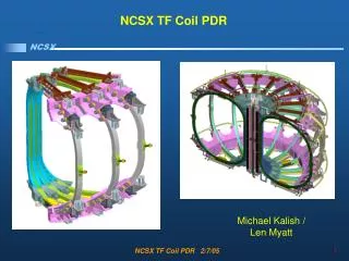
NCSX Modular Coil Welded Interfaces. Presented by the NCSX Engineering Team to the Edison Welding Institute May 30, 2007. NCSX. A NCSX Modular Coil. 1.2-m 46-in. 1.2-m 48-in. 1.0-m 38-in. 2.5-m 99-in. 2.8-m 109-in. 2.8-m 109-in. 2.1-m 83-in. 2.0-m 78-in. 2.3-m 90-in.

E N D
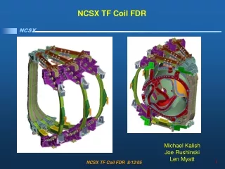
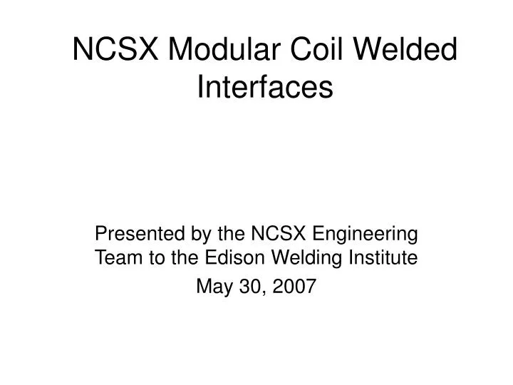
NCSX Modular Coil Welded Interfaces Presented by the NCSX Engineering Team to the Edison Welding Institute May 30, 2007
1.2-m 46-in 1.2-m 48-in 1.0-m 38-in 2.5-m 99-in 2.8-m 109-in 2.8-m 109-in 2.1-m 83-in 2.0-m 78-in 2.3-m 90-in The 3 Types of Modular Coil Castings Each casting weighs ~6000 lbs.
The Inner “Legs” of the Central Coils in a Field Period are Welded – Outer 2/3 of Perimeters are bolted. 5 welds/period (typ.) in central region.
Inner Leg Weld Regions • Major weld load: • Up to ~ 4.5 kips/inch of running load. A-A A-B B-C C-C Red indicates weld; note that C-C is not welded. These Pictures have inner leg bolts which are no longer in the design
Issues • Weld distortion. (See figure on right.) • Permeability of welds must be <1.02. Primary Issue: Will fillet welds here result in measurable distortion at the copper windings??
Inboard shims are cut to shape and thickness • Shim profile cut on water-jet and one side milled or ground flat • Other side milled to thickness at assembly • Shims made from stellalloy • Shims welded with Metaltek casting repair wire for low permeability
Weld design options depend on location • Flange edges about solenoid in some areas (red), shim must be flush (option B) • Other areas (non Straight) could use Option A A-A A-B Welds Flange A Option B Flange B B-C C-C Option A Preliminary analysis suggests a weld of 0.5 inch is sufficient
Weld design options depend on location • Flanges do not match up in some locations 1 ½’ ½” A-A A-B B-C C-C Option C
Weld Stresses Calculated with ANSYS Global Model Peak Stress of 19,246 psi BC Weld Stress Intensity for a 0.5 inch weld. Mesh of Global Model (sliding occurs on AB shim)
Derivation of Sm • Per the NCSX Structural Design Criteria, Sm shall be the lesser of 1/3 of the ultimate strength or 2/3 of the yield strength at temperature. • Since the weld region includes the Stelalloy casting, weld metal, HAZ, and shims made of 316-LN, the strength values shall be the lesser of these. • At this time, 316-LN for the shim material has not been finalized, so for the present we shall use the lowest values between the Stellalloy and the weld material at 77K. For the yield, this is 93.2 ksi for the C2 casting; 2/3 of yield =61.5 ksi. The lowest ultimate strength is 157.5 for the weld wire; 1/3 of this =52.5, so this is what we shall use. • A “knock down” factor of 0.6 shall be applied to this, since it is a butt joint. Therefore, the Sm=0.6*52.5=31.5 ksi. • Issue: What is required for fatigue? What stress concentration factor should be used for this type of weld?