Source Transformation
Source Transformation. Basis for Thevenin and Norton Equivalent Circuits. Objective of Lecture. Describe the differences between ideal and real voltage and current sources


Source Transformation
E N D
Presentation Transcript
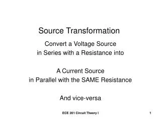
Source Transformation Basis for Thevenin and Norton Equivalent Circuits
Objective of Lecture • Describe the differences between ideal and real voltage and current sources • Demonstrate how a real voltage source and real current source are equivalent so one source can be replaced by the other in a circuit. • Chapter 4.4 Fundamentals of Electric Circuits
Voltage Sources Ideal Real • An ideal voltage source has no internal resistance. • It can produce as much current as is needed to provide power to the rest of the circuit. • A real voltage sources is modeled as an ideal voltage source in series with a resistor. • There are limits to the current and output voltage from the source.
Limitations of Real Voltage Source IL VL RL Real Voltage Source
Voltage Source Limitations (con’t) RL = 0W RL = ∞W
Current Sources Ideal Real • An ideal current source has no internal resistance. • It can produce as much voltage as is needed to provide power to the rest of the circuit. • A real current sources is modeled as an ideal current source in parallel with a resistor. • Limitations on the maximum voltage and current.
Limitations of Real Current Source • Appear as the resistance of the load on the source approaches Rs. IL RL VL Real Current Source
Current Source Limitations (con’t) RL = 0W RL = ∞W
Electronic Response • For a real voltage source, what is the voltage across the load resistor when Rs = RL? • For a real current source, what is the current through the load resistor when Rs = RL?
Equivalence • An equivalent circuit is one in which the i-v characteristics are identical to that of the original circuit. • The magnitude and sign of the voltage and current at a particular measurement point are the same in the two circuits.
Equivalent Circuits • RL in both circuits must be identical. IL and VL in the left circuit = IL and VL on the left IL IL 1 VL RL VL RL 2 Real Voltage Source Real Current Source
Example #1 • Find an equivalent current source to replace Vs and Rs in the circuit below. IL RL VL
Example #1 (con’t) • Find IL and VL. IL RL VL
Example #1 (con’t) • There are an infinite number of equivalent circuits that contain a current source. • If, in parallel with the current source, Rs = ∞W • Rs is an open circuit, which means that the current source is ideal. IL VL RL
Example #1 (con’t) • If RS = 20kW
Example #1 (con’t) • If RS = 6kW
Example #1 (con’t) • If RS = 3kW
Example #1 (con’t) • Current and power that the ideal current source needs to generate in order to supply the same current and voltage to a load increases as RS decreases. Note: Rs can not be equal to 0W. • The power dissipated by RL is 50% of the power generated by the ideal current source when RS = RL.
Example #2 • Find an equivalent voltage source to replace Is and Rs in the circuit below.
Example #2 (con’t) • Find IL and VL.
Example #2 (con’t) • There are an infinite number of equivalent circuits that contain a voltage source. • If, in series with the voltage source, Rs = 0W • Rs is a short circuit, which means that the voltage source is ideal.
Example #2 (con’t) • If RS = 50W
Example #2 (con’t) • If RS = 300W
Example #2 (con’t) • If RS = 1kW
Example #2 (con’t) • Voltage and power that the ideal voltage source needs to supply to the circuit increases as RS increases. Rs can not be equal to ∞W. • The power dissipated by RL is 50% of the power generated by the ideal voltage source when RS = RL.
Summary • An equivalent circuit is a circuit where the voltage across and the current flowing through a load RL are identical. • As the shunt resistor in a real current source decreases in magnitude, the current produced by the ideal current source must increase. • As the series resistor in a real voltage source increases in magnitude, the voltage produced by the ideal voltage source must increase. • The power dissipated by RL is 50% of the power produced by the ideal source when RL = RS.