Download
1 / 19
190 likes | 331 Views
Presentation 9 MAD MAC 525. Farhan Mohamed Ali (W2-1) Jigar Vora (W2-2) Sonali Kapoor (W2-3) Avni Jhunjhunwala (W2-4). W2. Design Manager: Zack Menegakis. 29 th March, 2006 Functional Block Simulations. Project Objective:

E N D
Presentation 9 MAD MAC 525 Farhan Mohamed Ali (W2-1)Jigar Vora (W2-2)Sonali Kapoor (W2-3) Avni Jhunjhunwala (W2-4) W2 Design Manager: Zack Menegakis 29th March, 2006 Functional Block Simulations Project Objective: Design a crucial part of a GPU called the Multiply Accumulate Unit (MAC) which will revolutionize graphics.
MAD MAC 525 Status: • Project chosen • Specifications defined • Architecture • Design • Behavioral Verilog • Testbenches • Verilog : Gate Level Design • Floor plan • Schematics and Analog Verifications • Layout of basic gates and small modules • Spring Break • Top level layouts, extractions, LVS, simulations (in progress) • To be done • Full chip layout and simulation
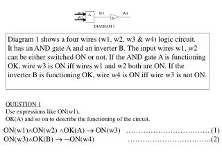
Block Diagram Input Input 16 Input 16 16 5 RegArray A RegArray B RegArray C 10 10 5 10 5 Multiplier Exp Calc Align 1 5 22 14 35 Control Logic & Sign Dtrmin Leading 0 Anticipator Adder/Subtractor 36 4 Normalize 14 1 5 Round Reg Y 1 10 5 15 16 Output 1 Ovf Checker
Design Decisions • Removed carry select top adder bits • Reduced hardware at the cost of speed • Speed still well within required parameters • Easier to layout
Pipelining Stages Reg C Multiplier Reg A Exp Calc Reg B Pipeline Reg Pipeline Reg Pipeline Reg Align C Pipeline Reg Pipeline Reg Adder Ld Zero Pipeline Reg Round Normalize Overflow checker Reg Y
Adder Schematic vs Layout • Layout is 19% slower than schematic • Layout = 1150ps • Schematic = 962ps • Other logic in adder module will slow it down further • Expecting about 1.6-1.8ns total • Well within 2ns target
Problems • Cadence refused to extractRC some of our modules • Turns out that Cadence discriminates against certain output pins for a reason we cannot yet determine • Solution was to copy output pins from modules that work when running extractRC and rename them • Certain group members not happy with group picture • Solution is to take a new picture, iron out the wrinkles & photoshop our project manager in