Building a 4x4x4 LED Cube with Microcontroller Control
This project details the construction and control of a 4x4x4 LED cube powered by a microcontroller. The cube is built using multiplexing techniques, allowing the layers and columns to be controlled efficiently. Each layer consists of 16 lights arranged in a grid that can be activated selectively through controlling voltage across the columns and layers. The code, written in C and compiled to PIC assembly, manages the LED illumination patterns. This cube serves as an advanced demonstration of microcontroller applications in visual displays.

Building a 4x4x4 LED Cube with Microcontroller Control
E N D
Presentation Transcript
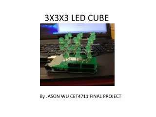
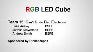
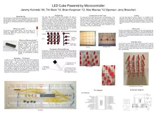
LED Cube Powered by Microcontroller Jeremy Kornwitz '09, Tim Beck '10, Brian Koopman '12, Max Macrae '12 (Sponsor: Jerry Breecher) • Multiplexing • The main idea behind powering and regulating the cube is multiplexing. The cube has four layers, each made up of 16 lights. There are 16 vertical columns composed of four lights each. The columns are hooked into the high voltage, while the layers are hooked into the low voltage. A light will only light up if its column and its layer have a voltage across it. (So if one layer and two columns are getting power, only two lights in that layer will light up). By controlling which layer and which column is getting power, we can turn specific lights on and off. The virtue of multiplexing is that it cuts down on the number of wires needed, but it requires that each layer be activated sequentially. This avoids unintentional LEDs being lit. Construction of the Cube The cube was built in layers with the help of a homemade jig. First, each horizontal layer was constructed in a 4x4 grid, connecting the cathodes to create a common layer. Then, the layers were stacked on top of one another, connecting the anodes. We ran into a problem here and had to use 16 individual connecting wires to connect the anodes. Once the layers were soldered together the cube was attached to the perf-board. Finally, four additional wires were connected to each horizontal layer so they could be activated. Coding The code that drives the cube is written in C, compiled to PIC assembly, and loaded on the microcontroller. The code uses two sections, the main level and the interrupt level, to send voltages to the proper pins to display a pre-programmed pattern. The two levels alternate thousands of times per second to create the image on the cube. What We Did We constructed a4x4x4 LED cube controlled by a PIC microcontroller with the ability for each LED to be addressed individually. Using an Interrupt Service Routine to illuminate LEDs at appropriate times we then applied our self-designed algorithms to display unique patterns on the cube. What is an LED? LED stands for light emitting diode. The short lead is the cathode, or negative side. The long one is the anode, or positive side. LEDs are commonly used in lights, including household flashlights. Main Level The main level initializes the variables to set up an interrupt timer and contains the information about the patterns. This code repeatedly sets or clears bits in a three dimensional array representing all the LEDs in the cube. If a LED's virtual representation is set to 1, it is turned on and vice versa. The pattern being used determines the order the LEDs are turned on and off. View of a Layer From the Top View of a Column From the Side Cathode Cathode ends, low voltage. LED What is a Microcontroller? A microcontroller is a small computer with a relatively simple CPU. It generally consists of a crystal oscillator to keep track of time, an interrupt mechanism to provide real time response to the events it controls, and a small amount of memory. Microcontrollers are used in virtually all automatically controlled devices. Interrupt Level A timer that runs while the main level is executing causes an interrupt thousands of times a second, bringing the program to the interrupt level. Each time the program gets to the interrupt level, it takes the contents of one level of the array and turns on the proper LEDs for that layer. The interrupts happen fast enough that all four levels appear to be on simultaneously. Anode end, high voltage. Building a Row The Jig Transistors (Pictured Below) The transistor is the main component that makes multiplexing feasible. Transistors are designed to manage electrical outputs; in this case the transistor acts as a gate to a low voltage area. Each of the four layers is connected to the (1) leg of the transistor, but no electricity will pass through the (3) ground leg until the (2) gate leg is also receiving power. Since each gate leg is connected to a pin on the chip, specific layers can be connected to ground at will by the chip. Hardware – The Board In order to run the cube, we need a power source and something to control the lights. The chip controls the lights by controlling the electrical output. In order to run the cube with minimum power, transistors are also used. The main idea is that once the chip has power running across it, the proper program can redirect that power through the lights using a set of transistors as the low voltage and the row of resistors in the bottom right as high voltage. Pin diagrams tell how to maintain a voltage across a chip so that it can do work, as well as naming each specific pin and detailing their uses. The board schematic also has specific instructions for connecting the chip to its programmer. These all come from the manufacturer. 3. Connects to a low voltage (ground). 1. Connects to a high voltage (source). Wire Diagram 2. Current can only flow from 1 to 3 if this is also receiving an output (a high voltage from source). Cube Attached to Perf-Board Schematic Diagram Pin Diagram The Board