
Data Link Layer Services
E N D
Presentation Transcript
CMPT 371Data Communications and Networking Chapter 5Data Link Layer 5: DataLink Layer
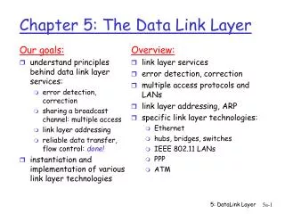
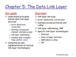
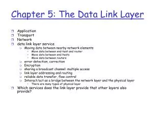
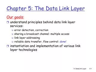
Our goals: understand principles behind data link layer services: error detection, correction sharing a broadcast channel: multiple access link layer addressing reliable data transfer, flow control: done! instantiation and implementation of various link layer technologies Chapter 5: The Data Link Layer 5: DataLink Layer
5.1 Introduction and services 5.2 Error detection and correction 5.3Multiple access protocols CDMA Aloha, CSMA/CD 5.4 Ethernet 5.5 Wireless links and LANs 802.11 (WiFi) Chapter 5 outline 5: DataLink Layer
Some terminology: hosts and routers are nodes (bridges and switches too) communication channels that connect adjacent nodes along communication path are links wired links wireless links LANs Data unit is a frame,encapsulates datagram “link” Link Layer: Introduction data-link layer has responsibility of transferring datagram from one node to adjacent node over a link 5: DataLink Layer
link layer implemented in “adaptor” (aka NIC) or on a chip Ethernet card, 802.11 card/chipset Combining hardware, software, firmware frame frame Where is the link layer implemented ! datagram rcving node link layer protocol sending node adapter adapter 5: DataLink Layer
Datagram transferred by different link protocols over different links: e.g., Ethernet on first link, frame relay on intermediate links, 802.11 on last link Each link protocol provides different services e.g., may or may not provide rdt over link transportation analogy trip from Princeton to Lausanne limo: Princeton to JFK plane: JFK to Geneva train: Geneva to Lausanne tourist = datagram transport segment = communication link transportation mode = link layer protocol travel agent = routing algorithm Link layer: context 5: DataLink Layer
Link Layer Services • Reliable delivery between adjacent nodes • we learned how to do this already (chapter 3)! • Q: why both link-level and end-end reliability? 5: DataLink Layer
Link Layer Services (more) • Flow Control (Chap 3): • pacing between adjacent sending and receiving nodes • Error Detection: • errors caused by signal attenuation, noise. • receiver detects presence of errors: • signals sender for retransmission or drops frame • Error Correction: • receiver identifies and corrects bit error(s) without resorting to retransmission 5: DataLink Layer
5.1 Introduction and services 5.2 Error detection and correction 5.3Multiple access protocols 5.4 Ethernet 5.5 Hubs, bridges, and switches 5.6 Wireless links and LANs Chapter 5 outline 5: DataLink Layer
Error Detection EDC= Error Detection and Correction bits (redundancy) D = Data protected by error checking, may include header fields • Error detection not 100% reliable! • protocol may miss some errors, but rarely • larger EDC field yields better detection and correction 5: DataLink Layer
Sender: treat segment contents as sequence of 16-bit integers checksum: addition (1’s complement sum) of segment contents sender puts checksum value into UDP checksum field Receiver: compute checksum of received segment check if computed checksum equals checksum field value: NO - error detected YES - no error detected. But maybe errors nonetheless? Internet checksum Goal: detect “errors” (e.g., flipped bits) in transmitted segment (note: used at transport layer only) 5: DataLink Layer
Example of checksum - Recall Segments 0110011001100110 0101010101010101 += 1011101110111011 0100010001000100 1’s complement 5: DataLink Layer
Parity Checking Two Dimensional Bit Parity: Detect and correct single bit errors Single Bit Parity: Detect single bit errors 0 0 5: DataLink Layer
5.1 Introduction and services 5.2 Error detection and correction 5.3Multiple access protocols 5.4 Ethernet 5.5 Hubs, bridges, and switches 5.6 Wireless links and LANs Chapter 5 outline 5: DataLink Layer
Multiple Access Links and Protocols Two types of “links”: • point-to-point • PPP for dial-up access • point-to-point link between Ethernet switch and host • broadcast (shared wire or medium) • traditional Ethernet • Satellite • 802.11 wireless LAN Or lecture room 5: DataLink Layer
Multiple Access protocols • single shared broadcast channel • two or more simultaneous transmissions by nodes: interference • only one node can send successfully at a time multiple access protocol • algorithm that determines how nodes share channel, i.e., determine when node can transmit • communication about channel sharing must use channel itself! • what to look for in multiple access protocols: 5: DataLink Layer
Ideal Mulitple Access Protocol Broadcast channel of rate R bps 1. When one node wants to transmit, it can send at rate R. 2. When M nodes want to transmit, each can send at average rate R/M 3. Fully decentralized: • no special node to coordinate transmissions • no synchronization of clocks, slots 4. Simple 5: DataLink Layer
MAC Protocols: a taxonomy Three broad classes: • Channel Partitioning • divide channel into smaller “pieces” (time slots, frequency, code) • allocate piece to node for exclusive use • Random Access • channel not divided, allow collisions • “recover” from collisions • “Taking turns” • speak only if “token” is at hand • tightly coordinate shared access to avoid collisions 5: DataLink Layer
Channel Partitioning MAC protocols: TDMA TDMA: time division multiple access • access to channel in "rounds" • each station gets fixed length slot (length = pkt trans time) in each round • example: 6-station LAN, 1,3,4 have pkt, slots 2,5,6 idle • Problem • unused slots go idle • More ? 6-slot frame 6-slot frame 3 3 4 4 1 1 5: DataLink Layer
Channel Partitioning MAC protocols: FDMA FDMA: frequency division multiple access • channel spectrum divided into frequency bands • each station assigned fixed frequency band • example: 6-station LAN, 1,3,4 have pkt, frequency bands 2,5,6 idle • Problem • unused transmission time in frequency bands go idle • More ? time frequency bands FDM cable 5: DataLink Layer
Channel Partitioning (CDMA) CDMA (Code Division Multiple Access) • Analogy • Public Key Encryption • Only the one holing the key can decrypt • Motivation • Sender – Mix information encoded with “codes” of receivers • Receiver – Decode mixed information using its own code, and find that for itself 5: DataLink Layer
Channel Partitioning (CDMA) CDMA (Code Division Multiple Access) • used mostly in wireless broadcast channels (cellular, satellite, etc) • unique “code” assigned to each user; i.e., code set partitioning • all users share same frequency, but each user has own “chipping” sequence (i.e., code) to encode data • encoded signal = (original data) X (chipping sequence) • decoding: inner-product of encoded signal and chipping sequence • allows multiple users to “coexist” and transmit simultaneously with minimal interference (if codes are “orthogonal”) 5: DataLink Layer
CDMA Encode/Decode 5: DataLink Layer
CDMA: two-sender interference 5: DataLink Layer
CDMA: two-sender interference Assume codes (1,-1) for recv1 (1,1) for recv2 Data bit 1 for recv 1: 1·(1,-1) Decoded using code for recv1: 1·(1,-1) ·(1,-1) =(1,-1) ·(1,-1)=2 Decoded using code for recv 2: 1·(1,-1) ·(1,1) =(1,-1) ·(1,1)=0 5: DataLink Layer
Frequency Hopping (origin of CDMA) • Frequency Hopping Spread Spectrum: transmitting radio signal by rapidly switching among many frequency channels, using a sequence known to both transmitter and receiver Google “Mother of CDMA” 5: DataLink Layer
Random Access Protocols • When node has packet to send • transmit at full channel data rate R. • no a priori coordination among nodes • two or more transmitting nodes -> “collision”, • random access MAC protocol specifies: • how to detect collisions • how to recover from collisions (e.g., via delayed retransmissions) • Examples of random access MAC protocols: • slotted ALOHA • ALOHA • CSMA, CSMA/CD (Ethernet), CSMA/CA (802.11 WLAN or Wi-Fi) 5: DataLink Layer
Assumptions all frames same size time is divided into equal size slots, time to transmit 1 frame nodes start to transmit frames only at beginning of slots nodes are synchronized if 2 or more nodes transmit in slot, all nodes detect collision Operation when node obtains fresh frame, it transmits in next slot no collision, node can send new frame in next slot if collision, node retransmits frame in each subsequent slot with prob. p until success Slotted ALOHA 5: DataLink Layer
Pros single active node can continuously transmit at full rate of channel highly decentralized: only slots in nodes need to be in sync simple Cons collisions, wasting slots idle slots nodes may be able to detect collision in less than time to transmit packet – but sill waste a slot clock 1 1 1 1 node 1 2 2 2 node 2 node 3 3 3 3 C E S C S E C E S Slotted ALOHA 5: DataLink Layer
Suppose a node transmits a frame in a slot with probability p prob that a node has success in a slot = p(1-p)N-1 prob that any node has a success = Np(1-p)N-1 For max efficiency with N nodes, find p* that maximizes Np(1-p)N-1 For many nodes, take limit of Np*(1-p*)N-1 as N goes to infinity: max efficiency 1/e = .37 Slotted Aloha efficiency Efficiency: long-run fraction of successful slots (many nodes, each with many frames to send) At best: channel used for useful transmissions 37% of time! 5: DataLink Layer
CSMA (Carrier Sense Multiple Access) CSMA: listen before transmit: • If channel sensed idle: transmit entire frame • If channel sensed busy, defer transmission • No time slot – fully distributed • Human analogy: listen and don’t interrupt others • Seems perfect – no collision ! (not really though) 5: DataLink Layer
“Taking Turns” MAC protocols channel partitioning MAC protocols: • share channel efficiently and fairly at high load • inefficient at low load: delay in channel access, 1/N bandwidth allocated even if only 1 active node! Random access MAC protocols • efficient at low load: single node can fully utilize channel • high load: collision overhead “taking turns” protocols look for best of both worlds! – but practically not 5: DataLink Layer
data data poll “Taking Turns” MAC protocols Type 1: Polling: • master node “invites” slave nodes to transmit in turn • Ask round-robin: do you have frame to send ? (e.g., USB polling) • concerns: • polling overhead • latency • single point of failure (master) master slaves 5: DataLink Layer
“Taking Turns” MAC protocols Type 2: Token passing: • control token passed from one node to next sequentially. • token message • concerns: • token overhead • latency • single point of failure (token) T (nothing to send) T data 5: DataLink Layer
5.1 Introduction and services 5.2 Error detection and correction 5.3Multiple access protocols 5.4 Ethernet 5.5 Wireless links and LANs Chapter 5 outline 5: DataLink Layer
Ethernet “dominant” LAN technology: • cheap $20 for 100Mbs! • first widely used LAN technology • Simpler, cheaper than competitors • Kept up with speed race: 10, 100, 1000 Mbps … Metcalfe’s Ethernet sketch 5: DataLink Layer
adapter doesn’t transmit if it senses that some other adapter is transmitting, that is, carrier sense transmitting adapter aborts when it senses that another adapter is transmitting, that is, collision detection Before attempting a retransmission, adapter waits a random time, that is, random access (Traditional) Ethernet uses CSMA/CD 5: DataLink Layer
Manchester encoding • Each bit has a transition • Allows clocks in sending and receiving nodes to synchronize to each other • no need for a centralized, global clock among nodes! 5: DataLink Layer
5.1 Introduction and services 5.2 Error detection and correction 5.3Multiple access protocols 5.4 Ethernet 5.5 Wireless links and LANs Chapter 5 outline 5: DataLink Layer
802.11b 2.4-5 GHz unlicensed radio spectrum up to 11 Mbps direct sequence spread spectrum (DSSS) in physical layer all hosts use same chipping code 802.11a 5-6 GHz range up to 54 Mbps 802.11g 2.4-5 GHz range up to 54 Mbps 802.11n (2009) 2.4/5GHz, MIMO IEEE 802.11 Wireless LAN • All use CSMA/CA for multiple access • All have base-station and ad-hoc network versions 5: DataLink Layer
Base station approach • Wireless host communicates with a base station • base station = access point (AP) • Basic Service Set (BSS) (a.k.a. “cell”) contains: • wireless hosts • access point (AP): base station 5: DataLink Layer
Ad Hoc Network approach • No AP (i.e., base station) • wireless hosts communicate with each other • to get packet from wireless host A to B may need to route through wireless hosts X,Y,Z • Applications: • “laptop” meeting in conference room, car • interconnection of “personal” devices • battlefield • IETF MANET (Mobile Ad hoc Networks) working group 5: DataLink Layer
IEEE 802.11: multiple access • Collision if 2 or more nodes transmit at same time • CSMA makes sense: • get all the bandwidth if you’re the only one transmitting • try to avoid collision if you sense another transmission 5: DataLink Layer
Enhancement: CSMA/CD ? • Collision detection doesn’t work: hidden terminal problem 5: DataLink Layer
Collision avoidance mechanisms • Problem: • two nodes, hidden from each other, transmit complete frames to base station • wasted bandwidth for long duration ! • Solution: • small reservation packets • nodes track reservation interval with internal “network allocation vector” (NAV) 5: DataLink Layer
Collision Avoidance: RTS-CTS exchange • sender transmits short RTS (request to send) packet: indicates duration of transmission • receiver replies with short CTS (clear to send) packet • notifying (possibly hidden) nodes • hidden nodes will not transmit for specified duration: NAV 5: DataLink Layer
Collision Avoidance: RTS-CTS exchange • RTS and CTS short: • collisions less likely, of shorter duration • end result similar to collision detection • IEEE 802.11 allows: • CSMA • CSMA/CA: reservations • polling from AP 5: DataLink Layer
Low-power, small radius, wireless networking technology 10-100 meters omnidirectional not line-of-sight infrared Interconnects gadgets 2.4-2.5 GHz unlicensed radio band up to 721 kbps Interference from wireless LANs, digital cordless phones, microwave ovens: frequency hopping helps MAC protocol supports: error correction ARQ Each node has a 12-bit address A word about Bluetooth 5: DataLink Layer
principles behind data link layer services: error detection, correction sharing a broadcast channel: multiple access link layer addressing, ARP link layer technologies: Ethernet, IEEE 802.11 LANs journey down the protocol stack now OVER! future stops: multimedia, security, network management Chapter 5: Summary 5: DataLink Layer
Finally: a day in the life of a web request • journey down protocol stack complete! • application, transport, network, link • putting-it-all-together: synthesis! • goal:identify, review, understand protocols (at all layers) involved in seemingly simple scenario: requesting www page • scenario:student attaches laptop to campus network, requests/receives www.google.com Link Layer