Download
1 / 20
200 likes | 355 Views
Progress of High Pressure Hydrogen Gas Filled RF Cavity Test Katsuya Yonehara Accelerator Physics Center, Fermilab MTA RF workshop Fermilab, November 15-16, 2010. 1. Prospect of HPRF cavity project. Short term (~ FY12). Demonstrate cavity under high radiation condition

E N D
Progress of High Pressure Hydrogen Gas Filled RF Cavity Test Katsuya Yonehara Accelerator Physics Center, Fermilab MTA RF workshop Fermilab, November 15-16, 2010 MTA RF workshop – HPRF R&D 1
Prospect of HPRF cavity project Short term (~ FY12) • Demonstrate cavity under high radiation condition • Investigate beam induced plasma in the cavity • Figure out beam loading effect and suppress it • Make a new cavity to test the modification technology • Provide information to high level management group • for RF technology selection (including with safety issue) Long term (FY13 ~) If the HPRF cavity is chosen as the RF technology • Make a realistic RF cavity • - Test in cryogenic condition • - Test in cooling channel fields • - Test gas regulation system • - etc… MTA RF workshop – HPRF R&D 2
Time table of HPRF beam test Time duration: 3~4 months 805 MHz button cavity test • MTA Radiation Shielding Assessment has been passed in • the local radiation safety committee at Fermilab • Beam will be available in January • Maximum rate 60 pulse/hr MTA RF workshop – HPRF R&D 3
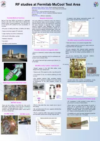
MTA beam line Final beam absorber • Beam profile: • Deliver 400 MeVH- beam in the MTA exp. hall • 1012 to 1013H-/pulse • Tune beam intensity by collimator and triplet • Reduce factor from full linac int. down to 1/40 or less MTA experimental hall MTA solenoid magnet 400 MeV H- beam MTA exp hall 400 MeV H- beam MTA RF workshop – HPRF R&D 4
Apparatus for beam test • No energized device within 15 feet from HP cavity due to • hydrogen safety issue • Beam must be stopped in the magnet due to radiation safety Elastic scattered proton from vacuum window (100~1000 events/pulse) 400 MeV H- beam • New apparatus: • New HPRF cavity • Beam extension line • Collimator+Beam absorber • Luminescence screen+CCD • Beam counter • RF circulator + damper • etc… (Ti) Bound electrons of negative Hydrogen will be fully stripped in the vacuum window Ex) Thickness = 4.5 g/cm3 × 0.1 = 0.45 g/cm2 Stripping cross section ~ 10-18 cm2 0.45/47.9 × 6.0 1023 = 5.6 1021 5.6 1021 10-18 = 5600 MTA RF workshop – HPRF R&D 5
RF modification & collimator RF coax line HPRF cell Collimator RF inlet beam Luminescence screen Gas inlet beam Support rail • Current status (11/15/2010) • New RF test cell has been delivered • Now Cu plating • New rail system has been delivered • New collimator has been delivered • Waiting for Cu electrode & Thread rod MTA RF workshop – HPRF R&D 6
Waveguide & circulator New 800 MHz Waveguide HPRF (1540 psi, 11/13/09) 5-T solenoid magnet HPRF cavity 400 MeV proton beam RF Circulator + Damper Solenoid magnet stage Schematic picture from Al Moretti’s hand drawing RF modulation due to reflected RF power • Current status (11/15/2010) • Al has a hand drawing of new wave guide system • Order pieces to extend wave guide • Al found the RF power damper and tested MTA RF workshop – HPRF R&D 7
Beam extension line Elastic scattered proton from vacuum window 400 MeV H- beam (Ti) • Current status (11/15/2010) • Discussed with engineer • Final drawing will come out soon • They expected two weeks of construction period MTA RF workshop – HPRF R&D 8
Detector system Elastic scattered proton from vacuum window 400 MeV H- beam (Ti) • Current status (11/15/2010) • Luminescence screen+ CCD have been delivered • We will use a telescope counter for beam monitor by using • existing plastic counters • Also use toroid coil for beam intensity monitor MTA RF workshop – HPRF R&D 9
Data acquisition system SiPM/PMT 1 2 3 4 5 6 RF Pickup 1 2 RF Forward 1 RF Return 1 Beam counter System trigger RF Klystron trigger MTA RF workshop – HPRF R&D 10 Gate
Fine timing calibration HPRF Digital Oscilloscope Optical feedthrough Acceptable polar angle ~ 45 mrad ps Laser SiPM/PMT ½” Heliax for RF pickup signal ½” Heliax for Optical signal Goal: Timing calibration < 100 ps • Current status (11/15/2010) • Ordered optical feedthrough • Preparing SiPM and optical fiber • ps Laser is ready MTA RF workshop – HPRF R&D 11
Study delay & distortion of signal in long cable • Giulia Collura (Summer student) made a fast laser circuit • by using avalanche trangister • Realize 0.6 ns timing resolution system • Laser diode was located in parallel to R3 • Similar test is planed by using < 10 ps Laser system Initial RF pickup signal Final signal after 300 ft ½’’ Heliax cable • She also investigated the distortion of signal in cable • No big signal distortion is observed • Phase shift due to dispersion was observed MTA RF workshop – HPRF R&D 12
Physics in HPRF plasma MTA RF workshop – HPRF R&D 13
Expected beam loading effect in HPRF cavity Simulated RF pickup signal in HPRF cavity with high intensity proton beam passing though the cavity • Beam loading effect: • Beam-induced ionized-electrons are • produced and shaken by RF field and • consume large amount of RF power • Such a loading effect was estimated as a • function of beam intensity • Recombination rate, 10-8 cm3/s are chosen • for this simulation • Scientific goals: • RF field must be recovered in few nano seconds • Measure RF Q reduction to test • beam loading model • Study recombination process in • pure hydrogen gas • Study attachment process with • electronegative dopant gas • Study how long does heavy ions • become remain in the cavity M. Chung et al., Proceedings of IPAC’10, WEPE067 MTA RF workshop – HPRF R&D 14
Electronegative dopant gas Damaged Cu electrode • SF6 and other Fluorine base gas has a large attachment • cross section • However, SF6 is dissociated and forms F-that damages • the cavity surface • Besides, cavity cannot operate in cryogenic temperature • lower than the boiling point of SF6 (209 K in STP) • NH3 has 1/1000 lower attachment cross section than SF6 but it • forms in H2 + N2 mixture gas due to beam energy deposition • Question is how much amount of N2 need MTA RF workshop – HPRF R&D 15
Diagnostic of plasma dynamics RF pickup signal in breakdown process • Spontaneous emission: • Solid line is a least square fitting of Lorentz • function by taking into account all points • Timing delay due to lifetime of de-excitation • Broadened Balmer line is observed • Stark effect well-explains resonance broadening • Plasma density 1018~1019 electrons/cm3 • Equivalent resonance circuit • Resonance circuit of normal RF • cavity consists of L and C • Breakdown makes streamer • It produces additional L and R • Resonance frequency is shifted • by them MTA RF workshop – HPRF R&D 16
Breakdown event in HPRF and vacuum (box) cavities Box cavity (0T, 0degree, 10/08/10) RF pickup B= 3T B= 0T Trig light X-ray Spec light (515.3 nm) 3 T, 0 degree (2010, 0820) • X-ray disappears in strong B fields • Trig light (white light) intensity is generally lower • in stronger field • Decay shape of RF pickup signal is modulated • by external fields • Spectroscopic measurement sometimes failed • due to human error, not physics RF pickup Trig light X-ray Spec light (515.3 nm) MTA RF workshop – HPRF R&D 17
Decay constants in HPRF and box cavity Breakdown τ in HPRF (various gas pressures) Breakdown τ in box cavity Low pressure High pressure 09/24/2008 • Time constant in HPRF cavity is 10 times faster than the box (vacuum) cavity • (Please be aware that the RF decay function in box cavity in strong fields are not really • exponential) • Clear RF frequency shifts are observed in the HPRF but not in the box cavity • Both indicate the plasma density in HPRF cavity is much denser than the box cavity MTA RF workshop – HPRF R&D 18
Critical issues for down selection • RF field must be recovered in few nano seconds • DC to 800 MHz, Hydrogen breaks down at E/P = 14. It indicates we can use DC data as a framework to explain results. • Need higher frequency measurements to test frequency dependence • Electrons move with a velocity, . Current . • Power dissipation due to electrons in phase with RF and dissipate energy through inelastic collisions = • Measurements with beam verify mobility numbers and verify our loss • calculation • Electrons recombine with positive ions and removed. If this is very fast they don’t load cavity, if slow cause trouble • Beam measurement will give the recombination rate • Solution: use electronegative gas(es) to capture electrons and form negative ions • Beam measurement will verify attachment rate • A+e →A- heavy negative ions. How long do these hang around and do they cause the breakdown voltage of the cavity to be lowered • Beam measurement will give necessary answers Feasibility including with hydrogen safety analysis also need to be answered MTA RF workshop – HPRF R&D 19
Collaborators Alan Bross, Al Moretti, David Neuffer, MiloradPopovic, Gennady Romanov, Vladimir Shiltsev, Alvin Tollestrup, Katsuya Yonehara (Fermilab) Chuck Ankenbrandt, Gene Flanagan, Rolland Johnson, GrigoryKazakevitch, James Maloney, MasaNotani(Muons, Inc) Ben Freemire, PierrickHanlet, Daniel Kaplan, Yagmur Torun (IIT) Moses Chung (Handong Global Univ.) Giulia Collura (Politecnicodi Torino) Andreas Jansson(European Spallation Source) Leo Jenner (Univ. College London) AjitKurup(Imperial College) Giovanni Pauletta (Univ. of Udine) MTA RF workshop – HPRF R&D 20