Download
1 / 29
310 likes | 372 Views
Learn about optical couplers, isolators, amplifiers, filters, multiplexers, and more. Understand key concepts such as dispersion, regeneration, and modulation methods. Explore the latest advancements and applications in optical signal processing.

E N D
Optical Couplers • Combines & splits signals • Light couples from one waveguide to a closely placed waveguide because the propagation mode overlaps the two waveguides • Wavelength independent or selective • Fabricated using waveguides in integrated optics • = coupling ratio • Power (Output1) = Power (Input1) • Power (Output2) = (1- ) Power (Input1) • Power splitter if =1/2: 3-dB coupler • Tap if close to 1 • -selective if depends upon • Lossless combining is not possible
8x8 Star Coupler Power from all inputs equally split among outputs
Isolators and Circulators • Extension of coupler concept • Non-reciprocal type will not work same way if inputs and outputs reversed • Isolator allows transmission in one direction, but blocks all transmission (e.g., reflection) in the other. • Circulator is similar to isolator, but with multiple ports.
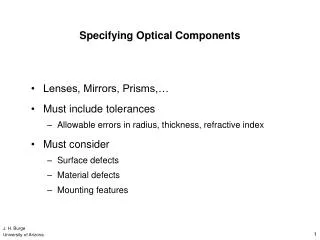
Filters • Low insertion (input-to-output) loss • Filter passband independent of temperature • Flat passband • Sharp skirts on the passband & crosstalk rejection
Gratings • Device using interference among optical signals from same source, but with different relative phase shifts (i.e. different path lengths)
Mux/Demux Using Cascaded Filters • Each filter passes one and reflects the other s • Very flat top and sharp skirts
40-80 km Terminal Terminal Regenerator - 3R (Reamplify, Reshape and Retime) 120 km Terminal Terminal EDFA - 1R (Reamplify) Terminal Terminal Terminal Terminal Terminal Terminal Optical Amplifiers versus Regenerators EDFA amplifies all ls EDFA is a common optical amplifier.
1R, 2R and 3R Regenerations 1R = Reamplify 2R = Reamplify, Reshape 3R = Reamplify, Reshape, Retime
Regenerators versus Optical Amplifiers • Regenerators specific to bit rate and modulation format used; optical amplifiers are insensitive. • A system with optical amplifiers can be more easily upgraded to higher bit rate without replacing the amplifiers. • Optical amplifiers have large gain bandwidths => key enabler of DWDM • Issues • Amplifiers introduce additional noise that accumulates. • Spectral shape of gain (flatness), output power, transient behavior need to be carefully designed.
WDM Multiplexing • TDM: 10Gb/s upper limit • WDM: Use multiple carrier frequencies to transmit data simultaneously B b/s 1 2 N NB b/s 1 2 N B b/s ...
Multiplexers, Filters, Routers • Filter selects one wavelength and rejects all others • Multiplexer combines different wavelengths • Router exchanges wavelengths from one input to a different output
Considerations in Switch • Number of switch elements: complexity of switch • Loss uniformity: different losses to different outputs (especially for large switches) • Number of crossovers: waveguide crossovers introduce power loss and crosstalk • Blocking: any unused input port can be connected to any unused output port
Crossbar Switch • Non-blocking • Shortest path length = 1 • Longest path length = 2n-1 • No crossover