Download
1 / 25
250 likes | 274 Views
Explore the current design, upgrade parameters, and reasons behind enhancing the interaction region in the PEP-II collider. Learn about the proposed upgrades, challenges, and the impact on beam dynamics and luminosity.

E N D
PEP-II Interaction Region Upgrade M. Sullivan for the Super-B Factory Workshop Hawaii January 19-22, 2004
Present design • Upgrade parameters • Why upgrade the IR • 1st IR Upgrade Attempt • Beta functions • Crossing angle • Present IR Upgrade Study • SR fans and power • SR backgrounds • Summary Outline
Machine Parameters that are Important for the IR PEP-II KEKB LER energy 3.1 3.5 GeV HER energy 9.0 8.0 GeV LER current 1.96 1.51 A HER current 1.32 1.13 A y* 12.5 6.5 mm x* 25 60 cm X emittance 50 20 nm-rad Estimated sy* 5 2.2 mm Bunch spacing 1.26 2.4 m Number of bunches 1317 1284 Collision angle head-on 11 mrads Beam pipe radius 2.5 1.5 cm Luminosity 7.21033 11.31033 cm-2 sec-1
PEP-II Proposed Upgrade Plans • Now Projected Upgrade • LER energy 3.1 3.1 3.1 GeV • HER energy 9.0 9.0 9.0 GeV • LER current 1.8 3.6 4.5 A • HER current 1.0 1.8 2.0 A • y*12.58.56 mm • x* 28 28 28 cm • X emittance 50 40 40 nm-rad • Estimated sy* 4.9 3.6 2.7 mm • Bunch spacing 1.89 1.26 1.26 m • Number of bunches 1034 1500 1700 • Collision angle head-on head-on head-on mrads • Beam pipe radius 2.5 2.5 2.5 cm • Luminosity 6.61033 1.81034 3.31034cm-2 sec-1
Why Upgrade (Initial motivations) • Lower the vertical beta function to 6-7 mm • Keep maximum betas low • Lower the beam-beam effect from the parasitic crossings • Possibly get enough separation to allow filling every RF bucket
Initial upgrade attempt • Replace the last 20 cm of each B1 magnet with quadrupole field (50% stronger than QD1 field) • Introduce a crossing angle to recover beam trajectories so we don’t have to redesign or move any magnets. We need a certain amount of separation at QF2. • Relatively easy change to make • Moves the focusing closer to the IP
Beta functions Low-energy beam Present design beta x* (cm) beta y* (mm) beta x max beta y max 50 15 94 112 35 12.5 135 135 50 6 75 277 With Initial Attempt 50 6 106 213 High-energy beam Present design 50 15 520 450 35 12.5 735 540 50 6 528 1085 With Initial Attempt 50 6 546 1057
Crossing angle and parasitic crossings • Crossing angle • Early last year, Ohmi-san from KEK announced that his beam-beam simulation code indicated a rapid luminosity degradation as a function of increasing crossing angle. Last summer, Yunhai Cai at SLAC confirmed Ohmi’s beam-beam result. The effect is most pronounced for very high tune shifts (~0.1). • Parasitic crossings • The introduction of a crossing angle increases the beam separation at the parasitic crossings which would lower the effect we presently see from parasitic crossings in by2 bunch patterns. Lowering by* also increases parasitic crossing effects since the by at the PC is larger.
Plot of luminosity degradation as a function of increasing crossing angle (courtesy of Yunhai Cai)
The tune shift from the first parasitic crossing normalized to the main collision tune shift as a function of crossing angle and plotted for various by* values for PEP-II (courtesy of Marica Biagini) LER PC tune shifts vs q/2 for different by* normalized to the IP tune shift for sl (bunch length) = 9 and 7 mm HER PC tune shifts vs q/2 for different by* normalized to the IP tune shift for sl = 9 and 7 mm
Present Working Design Constraints • Keep head-on collisions • Increase the beam separation at the 1st parasitic collision as much as possible • Allow for 6-7 mm by* • Do not change QF2 septum magnet
Present Working Design • Stronger B1 magnet to increase separation at 1st parasitic crossing 20% stronger first 5 slices (first 12.5 cm with the weakest field and the largest lever arm) • Slightly increase the beam energy asymmetry 9.1 x 3.08 GeV • Stronger, closer QD1 magnets 30% stronger slices for 1st 5 slices Move radial ion pump behind B1 to behind QD1 Put higher strength focusing in present pump place Minimal hardware change Higher strength material has higher temperature coefficient
Orbit comparison with upgrade and present design Work in progress 1st horizontal corrector +z side LER beam 1st vertical corrector
Work in progress 1st horizontal corrector +z side HER beam 1st vertical corrector
Steps toward a new design • Need to correct the position and angle in the x and y orbit on the +Z and –Z sides for each beam (8 orbits in total – two constraints for each orbit) • Too many variables for 8 total correctors • Allow adjusting the vertical collision point • Allow adjusting the horizontal collision angle • Allow the new sections of QD1 to have a variable offset (variable bending – but it affects both beams) • Allow (small) beam energy adjustments as long as we are still on the 4S resonance
Beta functions (revisited) Low-energy beam Present design bx* (cm) by* (mm) bx max (m) by max (m) 50 15 94 112 35 12.5 135 135 50 6 75 277 With upgrade #1 50 6 106 213 With upgrade #2 50 6 99 213 35 6 134 213 High-energy beam Present design 50 15 520 450 35 12.5 735 540 50 6 528 1085 With upgrade #1 50 6 546 1057 With upgrade #2 50 5 570 970 35 5 795 970
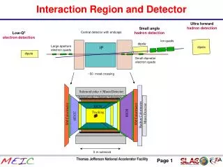
SR fans and power • The proposed high beam currents (4.5A LER and 2A HER) will generate a large amount of SR in the IR • The HER vacuum elements were designed for 2A so the HER parts should be OK. There is some question about the High-Power Downstream Dump that absorbs the HER B1 SR power • There are 2 vacuum chambers that see the LER SR power that need to be looked at more closely • The LER downstream crotch chamber that sees B1 radiation • The upstream LER SR mask for the Be beam pipe. It sees upstream QD1 radiation
SR fans and power (cont.) • The present power levels on the multi-tipped LER SR mask are about 30 W/mm at 2.1A beam current. This goes to 50 W/mm at 3.6A and 65 W/mm for 4.5 A of LER beam. This mask is under study. Presently it looks like this chamber may just work at 3.6 A but that it will need to be rebuilt for a 4.5 A beam • The crotch chamber design allowed for overlapping B1 radiation fans. This can only happen when the detector solenoid is off. We never intend to run high current beams with the solenoid off so we have some margin here.
SR backgrounds • The present LER SR mask (multi-tipped mask) does? (not completely checked yet) an adequate job of shielding the detector if we upgrade the B1 and QD1 magnets. We are trying to maintain the beam orbits such that the present design will work with minor modifications. • In any case, the extra power from the higher current LER beam means that SR backgrounds have to be studied in more detail • The very high beam current of the LER means that we need to check to make sure that back-scattered photons from the downstream crotch chamber do not strike the detector beam pipe
Summary • The initial upgrade proposal replaced the last 4 slices of the B1 magnets with quadrupole field. This allows for lower beta y* values with a smaller increase in the maximum beta y. • The replacement of the B1 slices with quad field introduces a ± 3.3 mrad crossing angle at the IP which reduces the beam-beam effect at the 1st parasitic crossing. However, recent beam-beam simulations indicate a luminosity reduction for beams with a crossing angle. • An alternative proposal currently under study is to strengthen the IP end of QD1 effectively moving the center of the magnet closer to the IP. At the same time, increase the beam separation at the 1st parasitic crossing by increasing the strength of the initial B1 slices. This maintains the PEP-II head-on collision. • The high beam currents of the upgrade plans generate significant SR power in the IR that must be handled • SR backgrounds look like they can be controlled but have not yet been thoroughly studied