Download
1 / 9
90 likes | 115 Views
Learn how to correctly install HV cables for the North and South parts of the aerogel detector. This comprehensive guide provides step-by-step instructions with numerical markings. Understand the arrangement and connection to the aerogel radiator as well.

E N D
Page 1 The notes about length of HV cables for the aerogel detector A.Litvinenko
Page 2 On the next four pages it is shown how the HV cables is installed for North part of detector and how it is proposed to be instolled for South part. The following numeration is used: 1. Counter have the identification marks consisting from whole number (from 0 to 79) and capital letter (N) or (S)for the North and South part respectively. The numeration is connected with aerogel radiator itself, start from the bottom of the two central columns and increase from bottom to top and from centre to the North (South) looking from collision point. 2. The identification marks for HV cable also consist from whole number (from 0 to 6) and capital letter (N) or (S)for the North and South part respectively.
Top view on HV cables Page 3 Collision vertex North South Cab.#6 (S) Wire 11-30 Spare Cab.#1(S) Wires 1-20 Cab. #2(S) Wires 11-30 Cab.#3(S) Wires 21-30 Cab.#4(S) Wires 1-10 Cab.#5(S) Wires 1-20 Cab.#6(S) Wires 11-30 Cab.#6 (N) Wire 1-10 Cab.#5 (N) Wire 21-30 Cab#3(N) Wires 1-20 Cab. #1N) Wires 21-0 Cab. #2 (N) Wires 1-10 Cab.#5(N) Wires 1-20 Cab.#4(N) Wires 1-10 Cab.#3(N) Wires 21-30 Cab#2(N) Wires 11-30 Cab.#1(N) Wires 1-20 Cab. #1(S) Wires 21-30 Cab. #2(S) Wires 1-10 Cab.#3(S) Wires 1-20 Cab.#6(S) Wires 11-30 Cab.#5(S) Wires 21-30 Cab.#6(S) Wires 1-10 South Cab.# 6(N) Wire 11-30 Spare North HV HV Rack Rack
Back (with respect to the collision vertex) view on the North HV cables . Page 4 69(N) 49(N) 29(N) 9(N) 68(N) 48(N) 28(N) 8(N) 67(N) 27(N) 47(N) 7(N) 66(N) 26(N) 46(N) 6(N) 45(N) 25(N) 65(N) 5(N) 64(N) 24(N) 44(N) 4(N) 63(N) 43(N) 23(N) 3(N) 22(N) 2(N) 62(N) 42(N) 41(N) 21(N) 61(N) 1(N) 20 (N) 60(N) 40(N) 0(N)
Front (with respect to the collision vertex) view on the North HV cables . Page 5 19(N) 39(N) 59(N) 79(N) 18(N) 58(N) 78(N) 38(N) 17(N) 37(N) 57(N) 77(N) 16(N) 56(N) 36(N) 76(N) 15(N) 35(N) 55(N) 75(N) 14(N) 34(N) 54(N) 74(N) 13(N) 33(N) 53(N) 73(N) 12(N) 32(N) 52(N) 72(N) 31(N) 11(N) 51(N) 71(N) 10(N) 30(N) 70(N) 50(N)
Back (with respect to the collision vertex) view on the South HV cables . Page 6 19(S) 39(S) 59(S) 79(S) 18(S) 58(S) 78(S) 38(S) 17(S) 37(S) 57(S) 77(S) 16(S) 56(S) 36(S) 76(S) 15(S) 35(S) 55(S) 75(S) 14(S) 34(S) 54(S) 74(S) 13(S) 33(S) 53(S) 73(S) 12(S) 32(S) 52(S) 72(S) 31(S) 11(S) 51(S) 71(S) 10(S) 30(S) 70(S) 50(S)
Page 7 Front (with respect to the collision vertex) view on the South HV cables . 69(S) 49(S) 29(S) 9(S) 68(S) 48(S) 28(S) 8(S) 67(S) 27(S) 47(S) 7(S) 66(S) 26(S) 46(S) 6(S) 45(S) 25(S) 65(S) 5(S) 64(S) 24(S) 44(S) 4(S) 63(S) 43(S) 23(S) 3(S) 22(S) 2(S) 62(S) 42(S) 41(S) 21(S) 61(S) 1(S) 20 (S) 60(S) 40(S) 0(S)
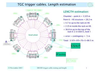
Page 8 View on the cables path fromdetector to the rack (from Thomas Shea ) .
Page 9 From the pages 3-7 one can see, that HV cable with the same # for North and South should have the different value if the distance from the end of the counters array to the corresponding rack is different for North and South (for South see page 8). Namely it is the following relation: L(Cab.#I(S)) = L(Cab.#I(N)) + L(C-R)_N - L(C-R)_S WereL(C-R)_N and L(C-R)_S are the lengths betweenthe end of the counters array to the North or South rack respectively Moreover the lengthsL_blueandL_white should be the same for North and South, and depend only from cable #. And only L_covered can be different for North and South: L _covered(Cab.#I(S)) = L _covered(Cab.#I(N)) + L(C-R)_N - L(C-R)_S But as it follows from Tomas datathe distances from the end of the counters array to the corresponding rack are the same for North and South (L(C-R)_N = L(C-R)_S ). It is mean that: the cables with the same numbers have to be the same for North and South (Cab.#I(S)=Cab.#I(N).