Download
1 / 19
190 likes | 211 Views
Learn to calculate residual pressure head at pipe outlet with various fittings. Step-by-step solution included.

E N D
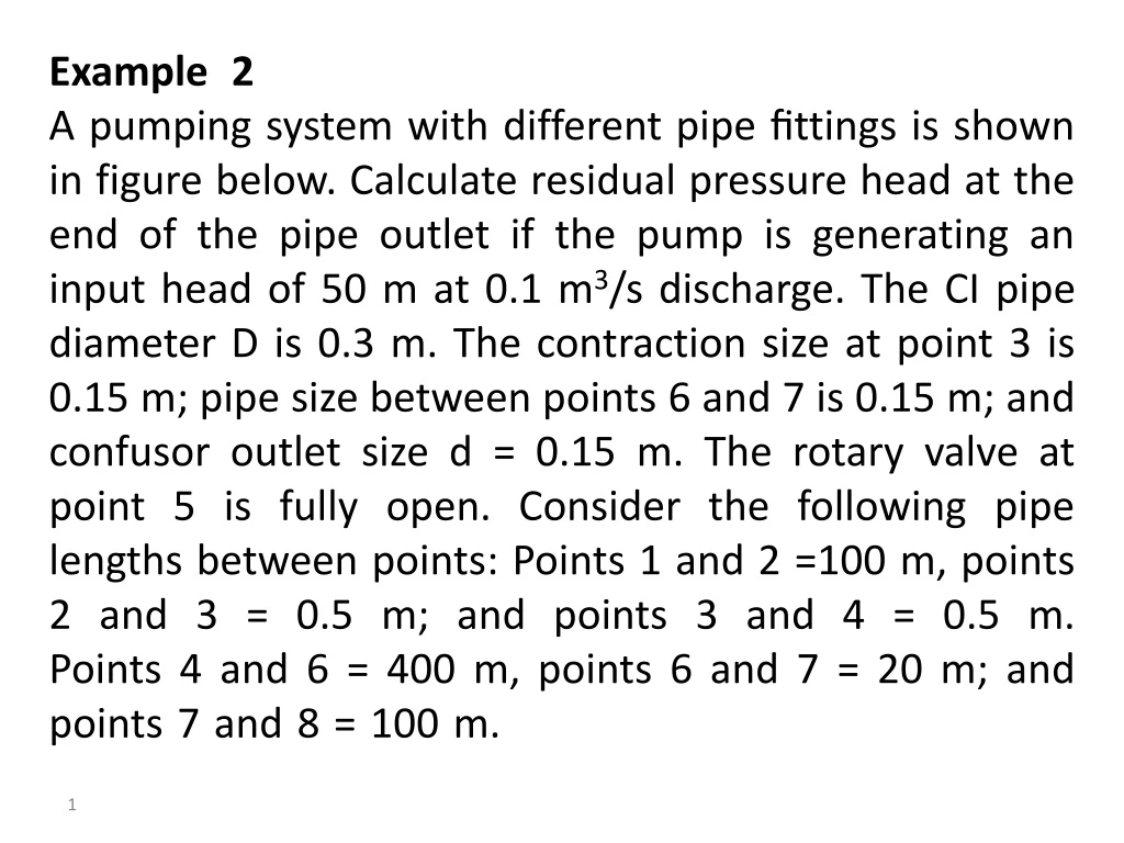
Example 2 ………………………………………………………………..A pumping system with different pipe fittings is shown in figure below. Calculate residual pressure head at the end of the pipe outlet if the pump is generating an input head of 50 m at 0.1 m3/s discharge. The CI pipe diameter D is 0.3 m. The contraction size at point 3 is 0.15 m; pipe size between points 6 and 7 is 0.15 m; and confusor outlet size d = 0.15 m. The rotary valve at point 5 is fully open. Consider the following pipe lengths between points: Points 1 and 2 =100 m, points 2 and 3 = 0.5 m; and points 3 and 4 = 0.5 m.Points 4 and 6 = 400 m, points 6 and 7 = 20 m; and points 7 and 8 = 100 m.……………………………………………….
Solution: 1. Head loss between points 1 and 2. Pipe length 100 m, flow 0.1 m3/s, and pipe diameter 0.3 m. calculate for temperature of 20 ○C:
Using Table 1 for CI pipes, is 0.25 mm. The friction factor f is calculated by using the following Eq. : Using the following equation to calculate the head loss hf12 in pipe (1–2) :
2. Head loss between points 2 and 3 (a contraction transition).For D = 0.3, d = 0.15, and transition length = 0.5 m, the contraction anglecan be calculated using the following Eq. : 2 tan-1 2 tan-1
3. Head loss between points 3 and 4 (an expansion transition).For d = 0.15, D = 0.3, the expansion ratio r =D/d= 2, and transition length = 0.5 m. calculate the expansion angle 2 tan-1 2 tan-1
4. Headloss between points 4 and 6. 1.012 *10-6 m2/s, , = 0.25 mm , D=0.3m, Q=0.1 m3/s, pipe length= 400m.
Using the following equation to calculate the head loss hf46 in pipe (4–6) : 5. Head loss at point 5 due to rotary valve (fully open). For fully open valve hm5=0 m
6. Head loss at point 6 due to abrupt contraction.For D = 0.3 m and d = 0.15 m, the form-loss coefficient will be:
7. Head loss in pipe between points 6 and 7.Pipe length = 20 m, pipe diameter = 0.15 m, and roughness height =0.25 mm.
The friction factor f is calculated by using the following Eq. :Using the following equation to calculate the head loss hf67 in pipe (6-7) :
8. Head loss at point 7 (an abrupt expansion). An abrupt expansion from 0.15 m pipe size to 0.30 m. Kf = 1
9. Head loss in pipe between points 7 and 8. Pipe length = 100 m, pipe diameter = 0.30 m, and roughness height =0.25 mm.
The friction factor f is calculated by using the following Eq. : Using the following equation to calculate the head loss hf78 in pipe (7–8) :
10. Head loss at outlet point 8 (confusor outlet). Calculate the form-loss coefficient: hm = Kf = Kf hm8 = 5.5 hm8 = 0.561 m
Total headloss : hL= 0.670 + 0.193 + 0.657 + 2.679 + 0 + 0.369 + 4.940 + 0.918 + 0.670 + 0.561 hL = 11.657 m Thus, the residual pressure at the end of the pipe outlet = 50 - 11.657 =38.343 m.


![[Head 1]](https://cdn3.slideserve.com/6227580/head-1-dt.jpg)