Download
1 / 60
610 likes | 639 Views
Learn how UML State Machines model dynamic behavior at various levels, from system to object, using transitions, self-transitions, decisions, and compound states. Explore examples with detailed explanations.

E N D
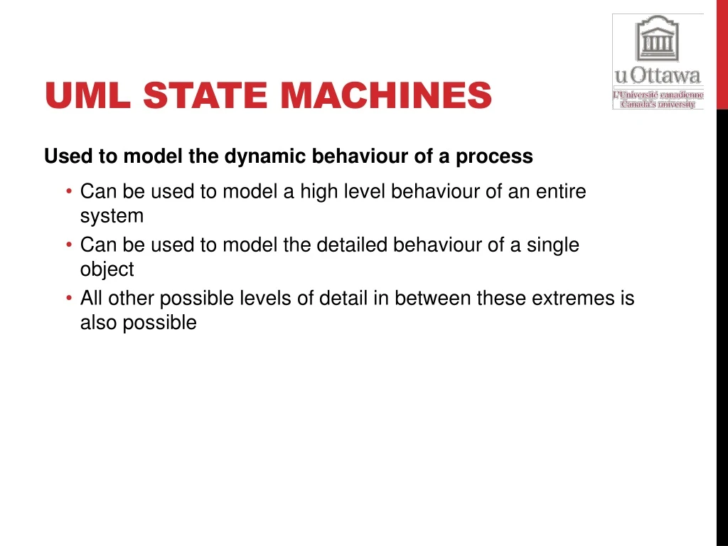
UML State Machines • Used to model the dynamic behaviour of a process • Can be used to model a high level behaviour of an entire system • Can be used to model the detailed behaviour of a single object • All other possible levels of detail in between these extremes is also possible
UML State Machine Example • Example of a garage door state machine • (We will come back to this example later)
States • Symbol for a state • A system in a state will remain in it until the occurrence of an event that will cause it to transition to another one • Being in a state means that a system will behave in a predetermined way in response to a given event • Symbols for the initial and final states
States • Numerous types of events can cause the system to transition from one state to another • In every state, the system behaves in a different matter • Names for states are usually chosen as: • Adjectives: open, closed, ready… • Present continuous verbs: opening, closing, waiting…
Transitions • Transitions are represented with arrows
Transitions • Transitions represent a change in a state in response to an event • Theoretically, it is supposed to occur in a instantaneous manner (it does not take time to execute) • A transition can have” • Trigger: causes the transition; can be an event of simply the passage of time • Guard: a condition that must evaluate to true for the transition to occur • Effect: an action that will be invoked directly on the system of the object being modeled (if we are modeling an object, the effect would correspond to a specific method)
State Actions • An effect can also be associated with a state • If a destination state is associated with numerous incident transitions (transitions arriving a that state), and every transition defines the same effect: • The effect can therefore be associated with the state instead of the transitions (avoid duplications) • This can be achieved using an “On Entry” effect (we can have multiple entry effects) • We can also add one or more “On Exit” effect
Self Transition • State can also have self transitions • These self transition are more useful when they have an effect associated with them • Timer events are usually popular with self transitions • Below is a typical example:
Coming back to Our Initial Example • Example of a garage door state machine
Decisions • Just like activity diagrams, we can use decisions nodes (although we usually call them decision pseudo-states) • Decision pseudo-states are represented with a diamond • We always have one input transition and multiple outputs • The branch of execution is decided by the guards associated with the transitions coming out of the decision pseudo-state
Compound States • A state machine can include several sub-machines • Below is an example of a sub-machine included in the compound state “Connected” Connected Waiting disconnect Disconnected receiveByte byteProcessed connect ProcessingByte closeSession
Compound States Example • Same example, with an alternative notation • The link symbol in the “Check Pin” state indicates that the details of the sub-machine associated with “Check Pin” are specified in an another state machine
Alternative Entry Points • Sometimes, in a sub-machine, we do not want to start the execution from the initial state • We want to start the execution from a “name alternative entry point” PerformActivity
Alternative Entry Points • Here’s the same system, from a higher level • Transition from the “No Already Initialized” state leads to the standard initial state in the sub-machine • Transition from the “Already Initialized” state is connected to the named alternative entry point “Skip Initializing”
Alternative Exit Points • It is also possible to have alternative exit points for a compound state • Transition from “Processing Instructions” state takes the regular exit • Transition from the “Reading Instructions” state takes an "alternative named exit point
Use Case – Validate PIN (1) • Use case name: Validate PIN • Summary: System validates customer PIN • Actor: ATM Customer • Precondition: ATM is idle, displaying a Welcome message.
Use Case – Validate PIN (2) • Main sequence: • Customer inserts the ATM card into the card reader. • If system recognizes the card, it reads the card number. • System prompts customer for PIN. • Customer enters PIN. • System checks the card's expiration date and whether the card has been reported as lost or stolen. • If card is valid, system then checks whether the user-entered PIN matches the card PIN maintained by the system. • If PIN numbers match, system checks what accounts are accessible with the ATM card. • System displays customer accounts and prompts customer for transaction type: withdrawal, query, or transfer.
Use Case – Validate PIN (3) • Alternative sequences: • Step 2: If the system does not recognize the card, the system ejects the card. • Step 5: If the system determines that the card date has expired, the system confiscates the card. • Step 5: If the system determines that the card has been reported lost or stolen, the system confiscates the card. • Step 7: If the customer-entered PIN does not match the PIN number for this card, the system re-prompts for the PIN. • Step 7: If the customer enters the incorrect PIN three times, the system confiscates the card. • Steps 4-8: If the customer enters Cancel, the system cancels the transaction and ejects the card. • Postcondition: Customer PIN has been validated.
ATM Machine Example • Validate PIN:
ATM Machine Example • Funds withdrawal:
Section 4 Behavioral Modeling
Topics • We will continue to talk about UML State Machine • We will go through a complete example of a simple software construction case study with emphasis on UML State Machines • End this section with some final words of wisdom!
Last Lecture • We have talked about UML State Machines • States and transitions • State effects • Self Transition • Decision pseudo-states • Compound states • Alternative entry and exit points • Today, we will tackle more advanced UML State Machines Concepts
History States • A state machine describes the dynamic aspects of a process whose current behavior depends on its past • A state machine in effect specifies the legal ordering of states a process may go through during its lifetime • When a transition enters a compound state, the action of the nested state machine starts over again at its initial state • Unless an alternative entry point is specified • There are times you'd like to model a process so that it remembers the last substate that was active prior to leaving the compound state
History States • Simple washing machine state diagram: • Power Cut event: transition to the “Power Off” state • Restore Power event: transition to the active state before the power was cut off to proceed in the cycle
Concurrent Regions • Sequential sub state machines are the most common kind of sub machines • In certain modeling situations, concurrent sub machines might be needed (two or more sub state machines executing in parallel) • Brakes example:
Concurrent Regions • Example of modeling system maintenance using concurrent regions Maintenance Testing testingCompleted Testing devices Self diagnosing shutDown diagnosisCompleted Idle maintain commandProcessed [continue] Commanding Waiting Processing Command commandProcessed [not continue] command
Orthogonal Regions • Concurrent Regions are also called Orthogonal Regions • These regions allow us to model a relationship of “And” between states (as opposed to the default “or” relationship) • This means that in a sub state machine, the system can be in several states simultaneously • Let us analyse this phenomenon using an example of computer keyboard state machine
Keyboard Example (1) • Keyboard example without Orthogonal Regions
Keyboard Example (2) • Keyboard example with Orthogonal Regions
Garage Door – Case Study • Background • Company DOORS inc. manufactures garage door components • Nonetheless, they have been struggling with the embedded software running on their automated garage opener Motor Unit that they developed in house • This is causing them to loose business • They decided to scrap the existing software and hire a professional software company to deliver “bug free” software
Client Requirements • Client (informal) requirements: • Requirement 1: When the garage door is closed, it must open whenever the user presses on the button of the wall mounted door control or the remote control • Requirement 2: When the garage door is open, it must close whenever the user presses on the button of the wall mounted door control or the remote control • Requirement 3: The garage door should not close on an obstacle • Requirement 4: There should be a way to leave the garage door half open • Requirement 5: System should run a self diagnosis test before performing any command (open or close) to make sure all components are functional
Client Requirements Motor Unit (includes a microcontroller where the software will be running) Wall Mounted Controller (a remote controller is also supported) Sensor Unit(s) (detects obstacles, when the door is fully open and when it is fully closed)
Use Case Diagram • Use Case Diagram Garage Door System Open Door include Run Diagnosis Close Door include Garage Door User
Run Diagnosis Use Case • Use Case Name: Run Diagnosis • Summary: The system runs a self diagnosis procedure • Actor: Garage door user • Pre-Condition: User has pressed the remote or wall mounted control button • Sequence: • Check if the sensor is operating correctly • Check if the motor unit is operating correctly • If all checks are successful, system authorizes the command to be executed • Alternative Sequence: • Step 3: One of the checks fails and therefore the system does not authorize the execution of the command • Postcondition: Self diagnosis ensured that the system is operational
Open Door Use Case • Use Case Name: Open Door • Summary: Open the garage the door • Actor: Garage door user • Dependency: Include Run Diagnosis use case • Pre-Condition: Garage door system is operational and ready to take a command • Sequence: • User presses the remote or wall mounted control button • Include Run Diagnosis use case • If the door is currently closing or is already closed, system opens the door • Alternative Sequence: • Step 3: If the door is open, system closes door • Step 3: If the door is currently opening, system stops the door (leaving it half open) • Postcondition: Garage door is open
Close Door Use Case • Use Case Name: Close Door • Summary: Close the garage the door • Actor: Garage door user • Dependency: Include Run Diagnosis use case • Pre-Condition: Garage door system is operational and ready to take a command • Sequence: • User presses the remote or wall mounted control button • Include Run Diagnosis use case • If the door is currently open, system closes the door • Alternative Sequence: • Step 3: If the door is currently closing or is already closed, system opens the door • Step 3: If the door is currently opening, system stops the door (leaving it half open) • Postcondition: Garage door is closed
Refine Behavioral Model – Motor Unit Running Open buttonPressed() [isFunctioning()] Timer (180 s) [! isFunctioning()] Closing doorOpen() buttonPressed(), [! isFunctioning()] buttonPressed(), obstacleDetected() [isFunctioning()] doorClosed() WaitingForRepair Closed Timer (180 s) [isFunctioning()] buttonPressed() [isFunctioning()] Opening buttonPressed() buttonPressed() HalfOpen
Refine Behavioral Model – Sensor Unit CheckingForObstacles [isObstacleDetected()] SendingObstacleEvent [!isObstacleDetected()] CheckingIfDoorOpen Time (20 ms) [isDoorOpen()] SendingOpenDoorEvent [!isDoorOpen()] CheckingIfDoorClosed [isDoorClosed()] SendingDoorClosedEvent [!isDoorClosed()] Sleeping
Coding • Whenever we are satisfied with the level of detail in our behavioral models, we can proceed to coding • Some of the code can be generated directly by tools from the behavioral model • Some tweaking might be necessary (do not use the code blindly) • Humans are still the smartest programmers
Sensor Class Sensor State machine Implementation
Umple Online Demo • UMPLE is a modeling tool to enable what we call Model-Oriented Programming • This is what we do in this course • You can use it to create class diagrams (structural models) and state machines (behavioral models) • The tool was developed at the university of Ottawa • Online version can be found at: http://cruise.eecs.uottawa.ca/umpleonline/ • There’s also an eclipse plugin for the tool