Download
1 / 46
460 likes | 476 Views
Explore radiation damage processes, electronic defects, and self-trapping in alkali halides and oxides. Discuss formation energies, activation energies for diffusion, and material resilience.

E N D
Radiation Defects in Alkali Halides and Oxides A.I. Popov Institute of Solid State Physics, University of Latvia, LV
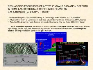
REI-15, Padova, Sept.1, 2009 Basic Properties of Radiation-Induced Point Defects in Halides and Oxides A.I. Popov, Max Planck Institute, Stuttgart and Institute of Solid State Physics, University of Latvia, LV E.A. Kotomin, Max Planck Institute, Stuttgart and Institute of Solid State Physics, University of Latvia J. Maier, Max Planck Institute, Stuttgart
The is no doubt that F center in AHC may be decribed as an electron trapped on anion vacancy.
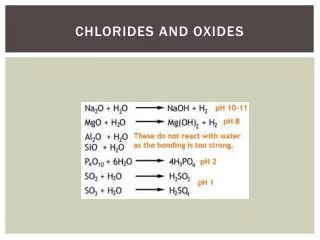
Optical absorption by F centers in alkali halides 1.Shape of the band is single Gaussian in almost all AHC K=K0exp[-a(hmax -h)2 2. The half-width depends on T [H(T)/H(0)]2=coth[h/2kT) 3. It was found experimentally that in alkali halides for F-band absorption the relation Eabs= 16.75 eV/(a Å)1.772 holds quite well!
Radiation Defects Ionizing radiation produces a variety of vacancy and intersitial type of point defects: In alkali halides: vacancy defects includes bare cation and anion vacancy, as well as halogen vacancy with one electron ( or F center). KCl - The activation energy for diffusion is found to increase monotonically in the series Vc, Va and F center1.19 eV, 1.44 eV and 1.64 eV In simple oxides: vacancy defects includes bare cation and oxygen vacancy, as well as oxygen vacancy with one or two electrons (F+ and F center). MgO- The activation energy for diffusion is found to increase monotonically in the series Vc, Va, F+ and F center (2.43, 2.50, 2.72, and 3.13 eV, respectively).
Radiation Damage Processes 1. Electronic processes 2. Elastic collisions Five types of radiation may produce displaced atom or ions (1) - rays, (2) energetic electrons, (3) thermal neutrons, (4) fast neutrons, (5) energetic atoms or ions 3. Radiolysis (1) Electronic excitation creation of an electronic defects (2) Conversion of this energy into kinetic energy of a lattice ion ion moves (3) The motion and stabilization of the ion The available energy, Egap (in fact Ex < Egap) > the formation energy of the Frenkel pair. the radiolysis can only occurs in insulators or wide band-gap semiconductors. The excitation must be localised on one atomic (or molecular) site Non-radiative transitions, allowing an efficient kinetic energy transfer to an atom, must prevail over radiative transitions
Could work in alkali halides (anions and cations) alkaline-earth halides Difficult in oxides
Elastic collisions Defect Production rate as a function of irradiation energy for MgO under electron irradiation. The damage rate is strongly dependent on the energy. Threshold for radiation damage. For relativistic particles such as electrons, the maximum energy Td (in eV) transferable from an incident electron of energy E (in MeV) to a lattice ion of mass number A is given by: Td =2147.7E(E + 1.022)/A
Displacement energy Other materials: II-VI ZnS 7-9/15-20 ZnSe 7-10/6-8 CdTe 6-9/5-8 CdSe 6-8/8-12 III-V GaAs 9/9.4 InP 6.7/8.7 InAs 6.7/8.3 Group IV C 25 graphite 35-80 diamond Si 13 Ge 13-16
F-H pair Formation in alkali halides: Self-trapped Exciton F-H pair
Resistant and sensitive materials • Resistant: • Metals, semi-conductors. • crystalline Oxides: • metastables (SrTiO3, MgO, Al2O3, c-SiO2) • Sensitive: • Alkali halides • Alkaline-earth halides CaF2, MgF2, SrF2 : • KMgF3, BaFBr, LiYF4: • Silver halides AgCl; AgBr • Amorphous solids a-SiO2 , a-As2Se3, a-As2S3, a-Se, a-As • Water and organic mater (bio matter)
Radiolysis versus ballistic damage • Radiolysis is not universal, not easily predictable • 2) Is in essence temperature dependent • 3) Spans over a wide time scale • 4) Occurs generally on one sub-lattice (anions) • 5) Radiolysis occurs occasionally • when it occurs, it is with a good energetic efficiency. Elastic damage occurs every time • but with a relatively poor energetic efficiency.
STE: BeO-YAG MgO, Al2O3 Charge-carriers self-trapping Self trapping of charge carriers results from a competition between deformation and polarisation of the lattice
Radiation Defects 1.Electronic defects, which involve changes in valence states Examples: KCl:Tl+ Tl+ +hole Tl2+ Tl+ +electron Tl0 MgO:Fe etc Fe2+ +hole Fe3+ Fe3+ +electron Fe2+ n-irradiated MgO
In this talk: • F center production in Cs-halides. Show the extension of Rabin-Klick diagram for all AHC. • Discuss differences between F center in AHC and F+ and F center in oxide materials (MgO as an example) • Discuss whether common and famous Mollwo-Ivey rule could be extended for oxide materials
RABIN AND KLICK DIAGRAM P D Townsend 1973 J. Phys. C: Solid State Phys.6 961-966 Data for Cs-halides with CsCl-structute are absent !!!
CsI Three different types of CsI crystals were studied in this paper. Nominally pure CsI crystals have been grown in the Laboratoire de Spectroscopie Atomique (CNRS/ISMRA, Caen). The low-doped CsI–Tl crystals with Tl+ ion concentration of about 1017 ion/cm3 have been supplied by Dr. P. Schotanus (SCIONIX, Holland). The highly doped CsI–Tl with Tl+ ion concentration of about 1019 ion/cm3 was obtained Institute of Solid State Physics, University of Latvia. Crystals have been irradiated at GANIL on the medium-energy beam line (SME) with 86Kr ions (8.63 MeV/amu). In this study, both the irradiation and in-situ measurements were done at 15 K.
F centre production in CsI crystals under ion irradiation at 15 K86Kr ions (8.63 MeV/amu) Evolution of the optical absorption spectra of CsI under irradiation at 15 K with fluences 1011 ions/cm2 (1); 3 × 10¹¹ ions/cm2 (2); 6 × 10¹¹ ions/cm2 (3); 9 × 10¹¹ ions/cm2 (4); 1.2 × 10¹² ions/cm2 (5); 1.6 × 10¹² ions/cm2 (6); 2.0 × 10¹² ions/cm2 (7). Production efficiency (eV/centre) of F band absorption for all cesium halides. CsCl - 7 × 10³ eV/centre S/D=0.43 CsBr - 8 × 10² eV/centre S/D=0.32 CsI - 2.5 × 10⁷ eV/centre S/D=0.17
Photoconversion of F+ centers in neutron-irradiated MgO Experiments and theory demonstrate that photon excitation of the positively charged anion vacancies at 5.0 eV releases holes that are subsequently trapped at V-type centers, which are cation vacancies charge-compensated by impurities, such as Al3+, F−, and OH− ions. A photoconversion mechanism occurs very likely via electron transfer to F+ centers from the quasi-local states which are induced in the valence band. INDO quantum chemical simulations of F+ centers confirmed the appearance of two induced quasi-local states located at 1.2 and 2.0 eV below the top of the valence band.
Hole Centeres in MgO V- center - hole trapped on an oxygen neighboring a cation vacancy. They are produced by UV-light, X-rays, or low-energy ions Optical absorption band at 2.3 eV A half-life time at RT: 2-7 year
Hole Centeres in MgO V0 center - two hole trapped on an oxygens neighboring a cation vacancy. Optical absorption band at 2.36 eV A half-life time at RT: 10 hours
Hole Centeres in MgO Impurity-related Vcenter holes are trapped oxygens neighboring a cation vacancy, which are charge compensators for impurities (OH-, F-, Al3+, Si4+ etc)
Photoconversion of F+ centers in neutron-irradiated MgO 3296 cm- 3323 cm-
Differential spectrum of the n-irradiated MgO crystals before and after UV irradiation for 50 min. Fe2+ +h+ → Fe3+.
During thermal annealing conversion F center colloid band NaCl, KCl, KBr etc 350 T 500 K MgO, Al203 etc ?????
MgO TCR samples The MgO crystals used were grown at the Oak Ridge National Laboratory using the arc fusion technique. The starting material was MgO powder from the Kanto Chemical Company, Japan. TCR was performed in a tantalum chamber at 2000 K and 7 atmospheres of magnesium vapor, followed by rapid cooling. This process produces anion oxygen vacancies, due to a stoichiometric excess of cations.
MgO: vacancy diffusion MgO- The activation energy for diffusion is found to increase monotonically in the series Vc, Va, F+ and F center (2.43, 2.50, 2.72, and 3.13 eV, respectively).
Dynamics of F-center annihilation in TCR MgO F concentration (a) sample N-1 2 x1017 cm-3 Activation energy = 1.9 eV (a) sample N-2 2 x1017 cm-3 Activation energy = 2.5 eV (c) sample N-3 5 x1018 cm-3 Activation energy = 3.4 eV To explain these observations, we suggest that a direct manifestation of the intrinsic diffusion of F centers is their diffusion-controlled aggregation to ultimately form nano cavities in the temperature range of 1400±1650 K. Eact is 3.4 eV which agrees well with the theoretical energy (3.1 eV) of the F-center elementary jump Eact values of 1.9 and 2.5 eV are significantly lower and hence can not be attributed to migration of single F-centers. Thus, in samples MgO I and MgO II oxygen vacancies are annihilated either by forming dimer centers with selected impurities, which favours their joint diffusion to internal sinks (such as dislocations and grain boundaries) or with more mobile defects (such as magnesium vacancies) Mg vacancy + F-center ionised F center
Dynamics of F-center annihilation in TCR MgO F concentration (a) sample N-2 2 x1017 cm-3 (b) (c) sample N-3 5 x1018 cm-3 Normalised concentration of (a) F centers in sample MgO II, (b) F centers in sample MgO III, (c) 3.59±3.35 eV absorption band in MgO III against isochronal annealing temperature. Assuming a first order kinetics, an activation energy for F-center diffusion was estimated for sample III to be 3.4 0.6 eV, in good agreement with theoretical calculations
Dynamics of F-center annihilation in TCR MgO 5 x1018 cm-3 Unexpected Results: brown coloration due to a broad extinction band centered at 3.59 eV (345 nm).
Nanocavities formation in MgO As the annealing temperature increased, the band became more intense, as it shifted toward lower energy. The band ultimately peaked at 3.35 eV It reached maximum intensity at 1673 K.
exp=345 nm From Mie theory: exp=320 nm This extinction band has been attributed to Mie scattering from nano-size cavities with typical dimensions of 3 nm, coated with magnesium metal.
Specimens for TEMstudies were prepared by mechanical grinding, dimpling, and argon ion-milling with an acceleration voltage of 5 kV and an incident angle of 10°. TEM, x-ray microanalysis, and electron diffraction studies were carried out in a Philips CM200 field-emission analytical electron microscope operated at 200 kV and equipped with a Be specimen holder. Electron microscopy: TCR sample after annealing at 1673K in a reducing atmosphere. Areas with a high concentration of dislocations were separated by regions in which only small rectangular features are observed
Optical absorption by F centers in alkali halides with NaCl structure F center in AHC was decribed as an electron trapped on anion vacancy It was found experimentally that in AHC for F-band absorption the relation Eabs= 16.75 eV/(a Å)1.772 holds quite well! Particle–in-a-box type model: E=3.14(i2+j2+k2)/2a2 Transition energy from GS(i=j=k=1) to the first excited state (2,1,1); (1,2,1) or (1,1,2) is given as Ea = 3(3.14)2/ 2a2 Particle–in-a-box type model ---> Electron in halogen vacancy
Optical absorption by F centers in alkali halides with CsCl structure
Mollwo-Ivey rule (extension) It was found experimentally that in alkali halides for F-band absorption the relation Eabs= 16.75 eV/(a Å)1.772 holds quite well! It works also for oxides (MgO, SrO, CaO) sulfids (CaS, SrS, BaS) This confirm: Particle–in-a-box type model ---> Electron in halogen (or oxygen, or sulphur) vacancy
Optical absorption spectra of MgO crystal 1) after TCR 2) after subsequent uv irradiation 3) after neutron-irradiation MgO crystal up to a dose of 6.9·1018 neutrons/cm2
Conclusion: • F center production in Cs-halides. Show the extension of Rabin-Klick diagram for all AHC. • Discuss differences between F center in AHC and F+ and F center in oxide materials (MgO as an example) • Show that famous Mollwo-Ivey rule could be extended for some simple oxide and sulfide materials with NaCl structure