Download

1 / 36
600 likes | 1.32k Views
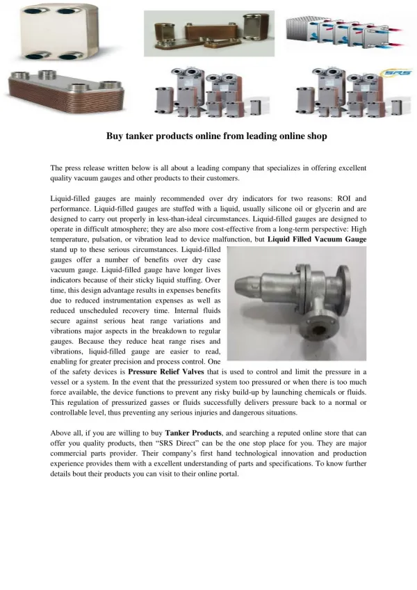
An Overview of Pressure Relief Devices. Jennifer F. Mize, PE Eastman Chemical Company Process Safety Services, TNO Plant Protection September 16, 2014. Agenda. Why are relief systems important? Types of vessels / allowable overpressure Types of relief devices Relief valves Rupture disks

E N D
An Overview of Pressure Relief Devices Jennifer F. Mize, PE Eastman Chemical Company Process Safety Services, TNO Plant Protection September 16, 2014
Agenda • Why are relief systems important? • Types of vessels / allowable overpressure • Types of relief devices • Relief valves • Rupture disks • Conservation vents • When is a relief evaluation required?
Why are relief systems important? • Relief systems are often the last line of defense against a serious overpressure incident • While they are technically classified as an active safety instrumented function (SIF), they generally do not give active feedback on their status, as they are standby devices. • Note: Emergency relief systems should NEVER be used for routine pressure control • They are generally a single device that is intended to protect against multiple potential overpressure scenarios • Therefore, proper design, specification, installation, maintenance, and testing are critical if relief systems are to fulfill their proper place in the overall safety layers of protection.
Undervacuum This damage occurred due to pumping out with a closed vent.
This damage occurred due to pumping out with the conservation vent covered by plastic.
Significant vacuum can result from collapsing vapors when an ESD is initiated on a distillation column.
Types of vessels / allowable overpressure • Types of vessels • MAWP < 2.5 psig API 650 • 2.5 psig < MAWP < 15 psig API 620 • MAWP > 15 psig ASME • Allowable overpressure • API 650: 1 x MAWP (No allowable overpressure) • API 620: 1.1 x MAWP, 1.2 x MAWP for fire case • ASME: 1.1 x MAWP or +3 psig, whichever is greater, 1.21 x MAWP for fire case • There is no allowable undervacuum for any vessel. • Other countries also have other design codes. • All vessels must have documented pressure and vacuum ratings before a relief evaluation can be done.
Determining appropriate set pressure • Set pressure for relief valves and rupture discs is most often equal to the vessel MAWP unless limited by connected equipment. • Set pressure for conservation vents must be below the MAWP for API 650 vessels. • Conventional conservation vents require 100% overpressure to be fully open. • The minimum overpressure for proper performance of a conventional conservation vent is 20%. • Set vacuum for conservation vents must be below the MAWV. PF = Flowing pressure (MAWP) PS = Set pressure
Relief Devices • Three major categories • Relief valves • Rupture disks • Conservation/pressure/vacuum vents • ASME code certification / UV and/or UD stamp • Relief devices with set pressures above 15 psig are certified by the National Board (relief valves and rupture disks) • Certifications are recorded in the Redbook (NB18) • NB18 is updated once a month • http://www.nationalboard.org/SiteDocuments/NB18/PDFs/NB18ToC.pdf
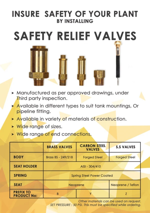
Relief valves • Automatically reclose when pressure excursion ends • Available set pressures ranging from 15 psig to 6000 psig • ASME “safety valves” for steam, gas, or vapor service exhibit quick-opening “pop” action and achieve full capacity at 10% overpressure • ASME liquid service “relief valves” are of modulating design (begin opening at set pressure and open further as pressure increases) • “Safety relief valves” can function as either a safety (pop) valve or as a modulating liquid relief valve, depending on the application
Conventional Safety Relief Valve (From API Standard 520, Part I, Figure 2)
Balanced Bellows Relief Valve(From API Standard 520, Part I, Figure 4)
Pop-Action Pilot Operated Relief Valve(From API Standard 520, Part I, Figure 6)
Relief valves • All spring-loaded valves have some hysteresis in their opening and closing characteristics. • Blowdown • Point at which the valve completely reseats • Typically 93% of set pressure (7% blowdown) • Manually adjusted, not tested • Simmer • Bubbles first pass around the edge of the disc, but the disc has not yet risen off the seat. • Occurs between 97% and 103% of the valve set pressure
Relief valves • Chatter • Chattering is the rapid opening and slamming shut of a disc on the seat. Chatter can quickly damage or destroy the valve internals. • If the inlet pressure drop exceeds the blowdown point, chatter can occur. • ASME Section VIII guidance (Appendix M, non-mandatory) and API Standard 521 recommend limiting inlet pressure drop to 3% of the set pressure. • Chatter is only experienced with compressible flow.
Relief valve certification • Relief valve certification testing is conducted using air, steam, and/or water • Relief valves can be certified for one, two, or all three media • Relief valves certified for gas/vapor and/or steam may provide a coefficient of discharge for non-code liquid service, usually at 25% overpressure • Relief valves certified for liquid (water) may use a liquid trim that is not certified for gas/vapor and/or steam • For ASME Code vessels, the relief valve must be certified for all flow types that could pass through the valve during a relief event
Rupture disks • Non-reclosing pressure relief devices • Can be used alone or in combination with a relief valve • Used alone when it is desirable to keep the relief line open after the disc has ruptured • OP/BP ratio very important • OP – operating pressure • BP – burst pressure • Types of rupture discs • Direct acting (forward) • Reverse acting • Flat discs (non-metallic) • Newer disk designs can achieve low burst pressures in small size disks (< 15 psig) • Should not be used in locations where water hammer can be experienced
Conventional (Tension Type) Rupture Disks(From API Standard 520, Part I, Figure 11)
Reverse Acting Rupture Disks(From API Standard 520, Part I, Figure 15) Knife blade designs should be used with extreme caution (knife blades used to burst the disc instead of scoring)
Rupture disks • Manufacturing range • The manufacturing range is the range of pressure within which the average burst pressure of test disks must fall to be deemed acceptable. • The disk will be stamped at the average burst pressure of all test disks. • Burst tolerance • Burst tolerance is the maximum variation from the stamped burst pressure. • Per ASME Code, Section VIII, Division 1, UG-127 (a)(1), the burst tolerance shall not exceed ± 2 psig for burst pressures ≤ 40 psig or ± 5% for burst pressures > 40 psig.
Rupture disks • Using manufacturing range and burst tolerance • Requested burst pressure: 100 psig • Burst pressure is typically equal to the vessel MAWP. • Direct acting rupture disks • Manufacturing range: +10% to -5% • Stamped burst pressure range: 95 psig to 110 psig • Burst tolerance: ±5% • Minimum and maximum actual burst pressure: 90.25 psig (min) / 115.5 psig (max) • Reverse acting rupture disks • Manufacturing range: 0% • Stamped burst pressure: 100 psig • Burst tolerance: ±5% • Maximum and minimum actual burst pressure: 95 psig (min) / 105 psig (max)
Rupture disk burst temperature • For typical installations, specify the burst temperature equal to the normal operating temperature. • If the disk is not located directly on the vessel, the actual temperature at the disk can be much closer to ambient temperatures than to the normal operating temperature. • The burst pressure increases as the temperature decreases. • This is a significant concern for rupture disks specified with elevated burst temperatures (>150 °F), since the increase in burst pressure due to lower temperature at the disk can exceed the typical overpressure allowances for a pressure vessel during a relief event.
Rupture disk / relief valve combinations • Why are rupture discs installed in series with relief valves? • Protect an expensive spring-loaded device from a corrosive environment • Give absolute isolation when handling extremely toxic chemicals • Give absolute isolation when handling flammable gases • Protect the relatively complex parts of a spring-loaded device from reactive monomers which could cause plugging • Relieve slurries which may plug spring loaded devices • Environmental concerns
Rupture disk / relief valve combinations • Space between the devices is susceptible to pressure buildup due to small leak in disk • If pressure is high enough, effective burst pressure of the disk can exceed allowable accumulation • Methods for detection of pressure buildup • Pressure switch/transmitter with remote indication and local manual bleed • Excess flow valves may be included to vent very small leaks • Excess flow valves and manual bleeds must be vented to safe location, such as the relief valve discharge line
Conservation vents • Reclosing devices used for low pressure applications (settings from 0.5 oz/in2 to 15 psig) • Can be used for emergency pressure relief (typically manway relief devices), vacuum relief, and/or normal breathing • Typically used on large, low pressure storage tanks and other low pressure vessels (< 15 psig) • API 650 • API 620
Conservation vents Weight-loaded pressure / vacuum vents End-of-line Pipeaway
Conservation vents Manway relief devices Pressure / vacuum manway relief device - hinged Pressure manway relief device - hinged
Conservation vents Pipeaway weighted pressure vent Weighted vacuum vent - top mount
Conservation vents • Design considerations: • Do not meet ASME Code requirements • Conventional designs require 80-100% overpressure to achieve full opening. • Special designs can achieve full opening at 10% overpressure. • Designed for gas or vapor flow ONLY • Selected based on manufacturer’s capacity curves/tables • Weighted designs are typically less expensive than spring-loaded designs. • Spring-loaded designs are available for settings greater than 1 psig.
Tank MAWP Set pressure Pressure curve for 4" Varec 2020A conservation vent
Tank MAWV (4" wc) Set vacuum Vacuum curve for 4" Varec 2020A conservation vent
When is a relief evaluation required? All vessels should have a relief evaluation. Update your relief documentation for: • Relief path sizing for a new installation • Replacement of an existing device or vessel • PHA requirements (relief documentation is required Process Safety Information) • Relief path piping modifications • Change in the relief device setpoint • Composition changes • Introducing flammable solvents in an area, even if only a transfer line passing through
Update your relief documentation for: • Change in pumping dynamics • Increase in the speed (RPM) of a pump motor • Increase in pump impeller diameter • Decrease in supply pipe equivalent length • Increase in utility temperature and/or supply pressure • Changes in control valve or supply piping • Decrease in condenser heat transfer area • Increase in heater heat transfer area All vessels should have a relief evaluation.