Download
1 / 20
200 likes | 339 Views
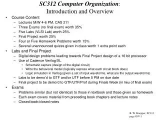
SC312 Computer Organization : Introduction and Overview. Course Content Lectures M/W 4-6 PM, CAS 211 Three Exams (no final exam) worth 35% Five Labs (VLSI Lab) worth 25% Final Project worth 25% Four or Five Homework Problems worth 15%

E N D
SC312 Computer Organization: Introduction and Overview • Course Content • Lectures M/W 4-6 PM, CAS 211 • Three Exams (no final exam) worth 35% • Five Labs (VLSI Lab) worth 25% • Final Project worth 25% • Four or Five Homework Problems worth 15% • Several unannounced quizes given in class worth 1 extra point each • Labs and Final Project • Digital design problems leading towards Final Project design of a 16 bit processor • Use of Cadence Verilog/XL • Schematic capture (design of the digital circuit) • Write the behavioral model (logically express what each circuit block does) • Logic simulation in Verilog (given a set of input waveforms, what are the output waveforms) • Labs to be demo’d to GTF and/or UTF before 5 PM on due date • Final project to be demo’d to GTF/UTF/Prof during Finals Week (in lieu of final exam) • Exams • Problems similar (but not identical) to those in textbook and those given as homework • Each exam covers material from preceding book chapters and lecture notes • Closed book/closed notes R. W. Knepper, SC312 page O/V-1
Introduction and Overview (continued): • Homework • Taken from text problems or other sources • Due at beginning of class on Due Date • Solutions will be discussed in class after grading • GTF will discuss homework problems at weekly Discussion Hours • GTF/UTF will grade homework • Objective of course: • To understand the basic organization and design of a digital processor (such as a PC) • To understand the design of digital systems (CPLD, FPGA, FSM) other than a processor • To understand memory hierarchy and memory system design • To understand and contrast RISC versus CISC instruction set architectures • To learn to use CAD tools (such as Cadence Verilog XL) to perform digital sys design • Prof • Ronald W. Knepper, Professor ECE, PHO 439, 3-0023 • GTF • Shameek Gupta, PHO 313, 3-0036 • UTF ? • A word about course evaluations (at end of semester) R. W. Knepper, SC312 page O/V-2
Some Base Logic Definitions • Combinational Logic • Logic circuit path which operates independent of any clock • Data flows through from input(s) to output(s) • Depends on circuit delays • Example: • NAND, AND, NOR, OR, Inverter, ripple bit adder • Any combination of above logic • Sequential Logic • Logic circuits which operate with a clock • Utilize latches and/or registers (also called flip-flops) • Data is valid only a certain phases of the clock • Typically edge-triggered to pass data along • Negative-going edge • Positive-going edge • Examples: • RS Flip-Flop, JK Flip-Flop, D Flip-Flop, T Flip-Flop • Finite State Machine (FSM) • Pipelined Microprocessor CPU • Combinational logic blocks interspersed between clocked registers R. W. Knepper, SC312 page O/V-3
Some Basic Memory Definitions • RAM = Random Access Memory • SRAM (Static Random Access Memory) • Dc powered – maintains data as long as power is ON • Volatile • High performance • Expense • Used for cache (L1 and L2) design • DRAM (Dynamic Random Access Memory) • Must be regenerated periodically (e.g. every 128 ms) or loses data • Volatile • Medium performance • Cheap • Used for main memory design • Magnetic Storage (also called Virtual Memory) • Partially serial access • Non-volatile – maintains data when power is OFF • Low performance • Very cheap • Used for disk drive and mass store devices R. W. Knepper, SC312 page O/V-4
Digital versus Analog Circuits: Which are they? • All digital circuits are really analog circuits designed to have outputs within the proper windows for definition of a logic “1” or a logic “0” (see below) • Inputs must also be within the prescribed range(s) for a logic 1 or logic 0 • For example, if the circuit is an inverter and the input is within logic 1 range below, the output will be within the logic 0 shown. • Noise Margin • The NM for a “1” is the signal range between the worst case low UP level of a circuit output and the minimum allowable voltage for a “1” at a subsequent input stage. • The larger the noise margin, the better the circuit is for combinatorial logic • CMOS has very good noise margins • The NM for a “0” is the signal range between the worst case high DOWN level of a circuit output and the maximum allowable voltage for a “0” at a subsequent input stage. R. W. Knepper, SC312 page O/V-5 John Wakerly, Digital Design: Principles & Practices, Chap’s 1,2,3
CMOS Inverter Input/Output Transfer Characteristic • CMOS inverter circuit operation: • Q1 is an N-channel FET • ON when Vin is high (Vgs > Vtn) • The source is at GND; drain is at Vout • Q2 is a P-channel FET • ON when Vin is low (|Vgs| > |Vtp|) • The source is at Vdd; drain is at Vout • CMOS inverter acts like a simple switch • When Vin is near GND, Q1 is OFF and Q2 is ON pulling Vout to Vdd • When Vin is near Vdd, Q1 is ON and Q2 is OFF pulling Vout to GND • DC Transfer Characteristic: • If Vin is slowly varied from GND to Vdd, Vout switches from Vdd to GND • But, Vout stays in the “1” state (near Vdd) until Vin gets close to ½ Vdd, and then switches quickly to the “0” state (near GND) for Vin greater than ½ Vdd R. W. Knepper, SC312 page O/V-6
CMOS Inverter Modeled as a Simple Switch • A very simple model for the CMOS inverter would treat the NFET and PFET transistors as simple SPST switches. • When Vin = low, NFET switch is open and PFET switch is closed • Implies that Vout = Vdd • When Vin = high, NFET switch is closed and PFET switch is open • Implies that Vout = GND R. W. Knepper, SC312 page O/V-7
2-input NAND Modeled as a Simple Set of Switches • We can apply the simple SPST switch idea to build a logic model for a 2-NAND • Q1 and Q3 are two NFET transistors in series which are ON when A and/or B are high • A high Q1 closed • B high Q3 closed • Q2 and Q4 are two PFET transistors in parallel which are ON when A and/or B are low • A low Q2 is closed • B low Q4 is closed • Logically, Z is low only if A and B are both high; if either A or B is low, Z is pulled high to Vdd by either Q2 or Q4, respectively. R. W. Knepper, SC312 page O/V-8
2-Input CMOS NOR Circuit • 2-input CMOS NOR circuit operation: • Q1 and Q3 are NFET transistors with sources at GND and drains at Z • If either A or B is high, Q1 or Q3 are ON and pull Z to GND • Q2 and Q4 are PFET transistors with sources at Vdd (Q2) and Q2/Q4 internal node (Q4) • If both A and B are low, Q2 and Q4 are both ON and pull Z high to Vdd • A simple SPST switch analogy can be used for the 2-input NOR, also. R. W. Knepper, SC312 page O/V-9
X gate Schematic Vgc = Vg P-FET Vdd Vout Gnd N-FET Vg -s in out s The CMOS Transmission Gate • A CMOS transmission gate is a very popular circuit used in MUX design and in pass-gate logic • Circuit Description: • The gate is comprised of an NFET transistor in parallel with a PFET transistor • The NFET transistor gate is connected to some control voltage (Vg) while the PFET gate is connected to the complement of Vg • Circuit Operation: • When Vg is high (and Vg’ is low), both the NFET and the PFET are ON • One is on harder than the other depending on whether Vin or Vout is at the higher potential • When Vg is low (and Vg’ is high), both the NFET and PFET are OFF since each transistor has its gate-to-source voltage Vgs less than its threshold magnitude |Vt| X-gate Symbol R. W. Knepper, SC312 page O/V-10
B0 B1 Vdd T6 T5 T4 T3 X0 X1 T1 T2 WL The SRAM Memory Cell • Circuit Schematic: • 4 NFETs and 2 PFETs: T1 & T2 called active devices; T3 & T4 called the I/O devices; T5 & T6 sometimes called loads. • The cell is comprised of two cross-coupled inverters (positive feedback). • 2 vertical lines (bit lines B0 & B1) are used for sensing state of cell and writing data in the cell • 1 horizontal line (word line WL) is used to select a row of cells for writing or reading and to prevent the unselected rows of cells from being disturbed. • Circuit Operation: • The cell has two stable states: “0” and “1” • “0” State = Node X0 high and Node X1 low; T2 & T5 are ON, T1 & T6 are OFF. • “1” State = Node X1 high and Node X0 low; T1 & T6 are ON; T2 & T5 are OFF. • No dc current flows in either state. • Write: raise WL to Vdd; pull one bit line high & pull the other bit line low • Read: raise WL to Vdd; precharge bit lines to ½ Vdd R. W. Knepper, SC312 page O/V-11
Data In Bit Addr Bit Decode (Column Decode) and Write Drivers Word Addr Word Decode (Row Decode) SRAM Cell 11 SRAM Cell 12 SRAM Cell 13 SRAM Cell 21 SRAM Cell 22 SRAM Cell 23 SRAM Cell 31 SRAM Cell 32 SRAM Cell 33 Sense Amplifiers and Off-Chip Drivers/Buffers Data Out SRAM Memory Array Organization • READ Operation: • Word Decode circuitry selects one of n word lines and drives high to Vdd (say WL2); other word lines held at gnd. • Bit Lines all precharged to half Vdd • Selected cell’s I/O devices turned ON and apply a DV to bit line pair • Sense amp triggers on bit line DV and stores read data “0” or “1” • WRITE Operation: • Selected WL is driven high to Vdd by word decode circuitry turning ON I/O devices in selected cells • Selected bit column has one BL pulled high to Vdd and the other pulled low to gnd, thus writing the selected cell. • Unselected bit columns merely perform a READ operation. R. W. Knepper, SC312 page O/V-12
Master D Latch Slave D Latch -QM D Q C C C C CLK The CMOS D Register (D Flip-Flop) • Circuit Schematic: • Comprised of two D latches tied in series with input D, output Q, and CLK control line • Each D latch is simply constructed out of two inverters cross coupled with a X-gate in the feedback loop and having a second X-gate in series with the input • Each X-gate switch C is closed if its control input is high (Vdd) and open if its control is low • Single clock fed directly (true) to 2nd latch (slave) and inverted to 1st latch (master). • Operation: (positive edge triggered) • When CLK goes to zero, master latch is opened to input D (feedback loop is disabled), while slave latch holds previous data and is closed to signal at node QM • When CLK goes to Vdd, master latch is isolated from input D (& feedback loop enabled) to hold data, while slave latch opens to receive data from master giving valid Q output R. W. Knepper, SC312 page O/V-13
Design Practicality: Try to minimize the # of transistors • Consider the design of a simple 2 input multiplexor (MUX) • Logically it can be described with four CMOS circuits (14 transistors) • Two 2-input AND’s (4 transistors each) • One 2-input OR (4 transistors) • One inverter (2 transistors) • In practice it is more likely to be built with only six CMOS transistors by using two complementary transmission gates and a CMOS inverter (as shown at left below) • If S is low, the upper transmission gate is closed (both transistors) and Z = A • If S is high, the lower transmission gate is closed (both transistors) and Z = B R. W. Knepper, SC312 page O/V-14
Design Precision: Circuit Timing Delay • Shown at the left is the logic circuit schematic for the function F=(XY) + (X’Y’Z) using basic CMOS AND’s, an OR, and two inverters • Each circuit has some intrinsic delay which depends on the CMOS technology and the circuit design • Outputs switch some time after the inputs switch by an amount of time equal to the basic gate delay • Any circuit design of several combinational logic stages tied together in serial fashion must take into account the delay through each circuit in order to prevent false (unexpected) logic levels • See waveforms at left R. W. Knepper, SC312 page O/V-15
Programmable Logic Devices • PLD (generic) • An IC where the logic function can be programmed into it after manufacture • In some cases, it can be reprogrammed if a bug in the design is discovered • PLA (programmable logic array) • The first PLD on the market • Two level AND/OR array structure with user programmable connections • PAL (programmable array logic) • Appeared on the scene after PLA’s • Lower cost • The MSI of the programmable industry; sometimes simply called PLD • ROM (read-only memory) • Originally not thought of as a programmable device at all – simply a memory for holding machine specific information, such as the control store operation • CPLD (complex programmable logic device) • A collection of PLD’s on a chip with programmable on-chip interconnections • FPGA (field programmable gate array) • Another scheme developed same time as CPLD • Large number of basic logic blocks (simple gates) with prog X/Y interconnection R. W. Knepper, SC312 page O/V-16
Programmable Logic Devices: CPLD vs FPGA • Complex Programmable Logic Device (CPLD): see (a) below • Most of today’s CPLD’s are simply a collection of PLD’s on a chip with interconnected by programmable interconnect (wiring) • Field Programmable Gate Array (FPGA): see (b) below • FPGA’s are comprised of basic logic blocks interconnected by X and Y wiring channels R. W. Knepper, SC312 page O/V-17
Integrated Circuit Design • IC design: • Chip • Wafer • Module • Board • Level of integration: • SSI – 1-20 gates/chip • MSI – 20-200 gates/chip • LSI – 200-200,000 gates/chip • VLSI – over 1,000,000 transistors/chip • In 2001 processor chips with over 100M transistors are being designed • Design Styles • Standard cell • Gate array • Full custom • Logic design tools • Schematic capture (Cadence Composer) • Logic behavioral description (Verilog or VHDL) • Logic simulation (Verilog XL) R. W. Knepper, SC312 page O/V-18
Technology Scaling and the Semiconductor IC Industry • Over the past 25-30 years the semiconductor industry has been improving technology by making continual advances in lithography and tooling, as well as, basic silicon device technology improvements and reduced power supply voltage. • A factor of 0.5X improvement in linear scale dimension roughly every 3 years has allowed a 4X increase in density (memory bits/mm2 or logic ckts/mm2) every 3 year generation • Named Moore’s Law for Gordon Moore of Intel who was the first to identify this expontial improvement and quantify it • Along with a 4X improvement in density every generation has come typically a 2X improvement in raw performance (device switching speed) • A continuation of Moore’s Law has allowed reductions in cost (per bit or per transistor) in an expontial fashion for the past 25-30 years • Resulted in low cost digital electronics and processor chips • Will Moore’s Law run out of gas? • Due to fundamental limits in IC technology physics, Moore’s Law is starting to slow • Gate oxide tunneling leakage current for Tox < 15-20 A • Transistor Ioff leakage becomes too high for Leff < 50 nm • Wide variation in device parameters (Vt, mobility) due to discrete doping atom effects • Researchers are looking for alternative materials to replace silicon, SiO2, etc. R. W. Knepper, SC312 page O/V-19
Processor Design versus Digital Logic Design • SC312 deals primarily with the design of processors • ALU/CPU/Registers • Memory and Virtual Store • Sequential logic design • Control unit • Pipelining • Instructions/microcode programmability • RISC vs CISC instruction set architecture (ISA) • We will touch briefly on other types of digital logic IC’s • FSM (finite state machine) • FPGA (field programmable gate array) • ASIC (application specific IC) • CPLD (complex programmable logic device) • Digital design is becoming pervasive in all areas of electronics: • Processors, controllers, and cores • Consumer electronics • Telecommunications/wireless • Automotive • Wired networking (routers, etc.) R. W. Knepper, SC312 page O/V-20