Download
1 / 45
480 likes | 751 Views
Magnetic control of a tokamak equilibrium. Jo Lister. CRPP-EPFL, Lausanne, Switzerland. With many thanks to all those with whom it has been such a pleasure to collaborate over the last few years Especially to Sun Hee Kim, for the film on the talk

E N D
Magnetic control of a tokamak equilibrium Jo Lister CRPP-EPFL, Lausanne, Switzerland With many thanks to all those with whom it has been such a pleasure to collaborate over the last few years Especially to Sun Hee Kim, for the film on the talk Keynote presentation for the 7-8 May workshop on Control for Nuclear Fusion, Eindhoven, the Netherlands Jo Lister, Control for Fusion, Eindhoven, May 7 2008
What are we watching ? Jo Lister, Control for Fusion, Eindhoven, May 7 2008
Contents • I attempt to provide a rapid overview of the control of the plasma equilibrium over the last 35 years…. • What is an equilibrium – what is a tokamak for our purposes ? • How do we control an equilibrium ? • When does an equilibrium become unstable ? • What work has been done over all these years, and why ? • What work remains to be done for ITER ? Warning: this is inevitably a very personalised view Jo Lister, Control for Fusion, Eindhoven, May 7 2008
Intro – Basics of a tokamak We are confining plasma (ionised gas) at 200,000,000 degrees, using a strong magnetic field (toroidal). The plasma is conducting and carries a large toroidal current. • We need: • a strong toroidal field to magnetise the plasma • a transformer to induce the plasma current • a field to create an equilibrium force That’s it, you now understand the tokamak Jo Lister, Control for Fusion, Eindhoven, May 7 2008
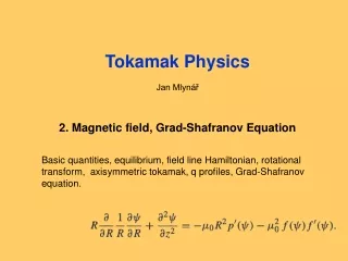
Intro – An equilibrium Unfortunately, the plasma will not just sit there – there are internal (gas) pressure and electromagnetic pressure – they both force the plasma to grow in radius Force is of the order: Tesla * MAmp * 2pR Mass is of the order: 800m3 * 1020 (per m3) * 10-27 (kg/ion) F = m a – the plasma will move very fast (msec) to find a force balance 2 modelling options are used - follow the acceleration - assume the plasma is always in “instantaneous force balance” (easier) Shafranov Equation We already have 2 different physics modelling approaches Jo Lister, Control for Fusion, Eindhoven, May 7 2008
• X X • Intro – We don’t have to react that fast We do not have to react on this timescale, which would be very difficult Why – Lenz’s law (1834) “When a magnetic flux changes, currents are induced to counter the change” The plasma sits in a metal vacuum vessel. If it moves, currents are induced in the vessel, and these create a magnetic field which counteracts the movement. We do not have to control the plasma movement We cannot control the plasma movement Jo Lister, Control for Fusion, Eindhoven, May 7 2008
8 6 g5 4 g4 2 g6 g3 0 Z (m) -2 g1 -4 g2 -6 -8 0 2 4 6 8 10 12 R (m) Intro - Equilibrium control is via imposed fields Gaps (control targets) PF coils ITER is large – powerful actuators Jo Lister, Control for Fusion, Eindhoven, May 7 2008
Intro - Control of an equilibrium is mastered TCV has a very wide range of magnetic configurations What we are showing is isoflux contours, surfaces containing magnetic field lines These are also contours of kinetic pressure P = n T (ions plus electrons) Equilibria are well understood Jo Lister, Control for Fusion, Eindhoven, May 7 2008
Intro – How are these shapes made in (e.g.) TCV ? For today, let’s think of the coil currents as controlling the magnetic field configuration which pulls and pushes on the edge of the plasma Jo Lister, Control for Fusion, Eindhoven, May 7 2008
Intro – Back to the equilibrium model The radial force balance, FR = Ip x Bv Time-varying Non-linear Radial equilibrium is non-linear and time-varying Any LTI model is locally linearised and approximate (film…) Jo Lister, Control for Fusion, Eindhoven, May 7 2008
Intro – What if our vertical field is not vertical ? Radial force balance assumes a vertical field In reality this field will not be homogeneous To next approximation, assume it is gently curved We have 2 cases, inward curvature and outward curvature Jo Lister, Control for Fusion, Eindhoven, May 7 2008
Intro – Unstable and stable curvature Inward curvature Created by a parallel inner current Pulls the plasma current – stable vertically • Outward curvature Created by an anti-parallel outer current Pushes the plasma current – unstable vertically X More current Better tokamak Jo Lister, Control for Fusion, Eindhoven, May 7 2008
• • X X Intro – Instability timescale Lenz’s law comes back again to help us – - the metallic vacuum vessel does not let the flux get out, or in… Although the system is unstable (destabilising force), the image currents generate an equal stabilising force (instantaneous force balance) But…. The metallic vacuum vessel is resistive –image currents decay, and then the plasma will move, and induce more current, and move again…. So the vertical instability now takes place on the timescale of the vacuum vessel image current decay time TCV, DIII-D up to 3000 / second ITER, around 14 / second Jo Lister, Control for Fusion, Eindhoven, May 7 2008
Introduction resumé (with apologies) Plasma equilibrium is understood, good experimental and theory bases Non-linear time-varying equations are available There can be a positional instability Complex equilibria have many coils which push and pull on the plasma Forces are huge Actuators are voltages on “Poloidal Field” coil circuits Equilibrium has to be precise to stop 200,000,000 degree plasma from destroying the wall Mastering the equilibrium presents an interesting control challenge Jo Lister, Control for Fusion, Eindhoven, May 7 2008
Progress – Pre-programmed control of radial position Late 1960’s – first tokamaks, a few milliseconds Short pulses in a vacuum vessel, equilibrium provided by Lenz’s law Then try to make longer pulses, bigger currents Need to add some vertical field to compensate the dissipating image currents Programme capacitor banks to fire current into simple “PF” coils Not what you want ? Do it again, keep adjusting the capacitor firing programme until you are happy – measure tokamak performance… Feedforward control was enough for the first tokamaks Jo Lister, Control for Fusion, Eindhoven, May 7 2008
Progress – Feedback control of radial position Scientists got both bored and more demanding (around 1973) DITE tokamak – Hugill, Sheffield (UKAEA) developed closed loop control of the radial position a) measurement can’t measure radial position can measure magnetic fields can infer position from available data b) actuator has to be a true power supply more expensive, remember these were cheap experiments c) controller Shafranov equation gives the correction sign, keep adjusting gain Stable equilibria were easily controlled Jo Lister, Control for Fusion, Eindhoven, May 7 2008
Progress – Control of shape JET was a huge jump in size, and was designed to have a non-circular plasma, elongated vertically shape control vertical stability But we had a full equilibrium equation (Grad-Shafranov) which tells us what the currents should be in the coils to get a chosen shape This was enough to design the PF coil system (correctly) and to start (Noll) worrying about the vertical instability (late 1970’s early 1980’s) Simple controllers were designed to change the shape, and were adjusted by hand by people who really understood the physics of shape control Jo Lister, Control for Fusion, Eindhoven, May 7 2008
Vessel circuit Power Supply X Progress – Understanding the vertical instability A basic understanding of the vertical instability was necessary to stabilise the first elongated shaped plasmas, in the early 1980’s (you don’t “learn” stabilisation by trial and error …) Keller (CRPP) and Noll (JET) derived simple models for INTOR with a filament plasma and a pair of filament conductors representing currents induced in the vacuum vessel if the plasma current moved vertically. Plasma mass was zero. The result was a set of coupled equations giving a second-order system with one unstable pole and one stable pole. This understanding is still intact – what we have done is to add lots of detail ! Simple models were/are adequate to derive stabilising controllers Jo Lister, Control for Fusion, Eindhoven, May 7 2008
Progress – Refining vertical instability Late 1980’s, in preparation for the Lausanne TCV tokamak, Lazarus (GA), Lister (CRPP) used a model with an eigenmode description of the vacuum vessel and an equilibrium vertical field. Analysis took the first up-down anti-symmetric eigenmode and explored controller design analytically. The DIII-D active PF coils were included in the analysis. The role of different coils was studied. The role of the inboard coils was identified analytically (“hybrid control” planned for ITER). The role of PD controllers was also studied analytically. The result was a proposed improvement to DIII-D stability, a record 2.5 elongation, to be broken only later by TCV. Note this was perhaps the last serious work done without Matlab ! Simple models led to basic understanding to advance performance Jo Lister, Control for Fusion, Eindhoven, May 7 2008
Progress – Maximising vertical stability TCV was built with coils inside the vacuum vessel to avoid the filtering action of the vessel image currents Minimising the delays in the loop and taking care of the estimator of the vertical position led to stabilisation of growth rates up to 3000/sec (Hofmann, Dutch, Moret - CRPP) Plasma elongations up to 2.95 were obtained and plasma currents up to 1MA demonstrated the gain in performance The cost is control fragility Jo Lister, Control for Fusion, Eindhoven, May 7 2008
Progress – Defining the ITER challenges Now mid-1990’s. ITER is on the horizon, control of shape and position is clearly crucial since the required precision is high, the control powers and voltages have to be minimised and robustness has to be high Effort was put into studying the shape and position control problem more experimentally, involving expertise from outside the tokamak experimental groups. TCV was encouraged to start collaborations on different topics with: Imperial College (UK) CREATE consortium (Italy) EPFL automation JAERI Jo Lister, Control for Fusion, Eindhoven, May 7 2008
Progress – Model-based controllers In the 1980’s, work started on model based controllers, Examples of this are Portone (NET, Imperial College) and Garriba (JET). Although Garriba developed LQG controllers for JET, to my knowledge they were never used in anger. …. But we just made a jump… where is the model ?? We have to convert the non-linear time-varying problem into an LTI model, specifically generating the common A,B,C,D(=0) matrices. Various approaches have been tested, and survive. Warning: LTI models are local approximations Jo Lister, Control for Fusion, Eindhoven, May 7 2008
Progress – Improving the models Two classes of ab initio model were developed: - deformable models for shape and position control - rigid distribution models for position control, especially stabilisation Model cross-comparison on TCV (CREATE model, RZIP model, Hofmann model) showed very close agreement, except for exceptionally shaped TCV equilibria (Hofmann, Dutch, Vyas, Lister – CRPP) Unsurprisingly, they all agreed well with experimentally measured growth rates. But… the models all depend on approximate engineering information on the construction of the tokamak and of the sensors, and also of the actual equilibrium when comparing with experiments. Jo Lister, Control for Fusion, Eindhoven, May 7 2008
Progress – Validating ab initio models Before model-based controllers were designed for TCV, the ab initio model to be used (CREATE-L) was validated experimentally with CREATE (Vyas,Lister-CRPP, Villone-CREATE and Bandyopadhyay–India). Square-wave and multi-harmonic stimulation was used Agreement was good – whatever “good” means Done in time and frequency domains. Jo Lister, Control for Fusion, Eindhoven, May 7 2008
Progress – H One goal of this procedure on TCV was to demonstrate that the superior performance of an H controller really could be obtained. On the basis of the ab initio validated CREATE-L model, an H controller was designed (Pironti, Ariola – CREATE) and deployed on a digital control system on TCV built for this purpose. After 1 failed attempt due to misunderstanding, the controller worked shadowing the standard controller and then replaced it for the following pulse. Mission accomplished. “So you will always use this controller ? Actually… no…. Warning: what is the “best” controller Jo Lister, Control for Fusion, Eindhoven, May 7 2008
Progress – Black box identification The interest of Imperial College increased and a PhD was undertaken to make a black box System Identification model of TCV (Coutlis). Random Binary Sequence and Multi-Harmonic stimulations were used and a “good” result was obtained. Experience with the technique was gained, but we already had a reasonable ab initio model. Jo Lister, Control for Fusion, Eindhoven, May 7 2008
Progress – Grey box identification The accuracy of the RZIP model (rigid current distribution) surprised the ITPA and a project was launched to compare on JT-60U. A PhD (Sharma-Imperial) used multi-harmonic frequency response experiments were compared with the ab initio RZIP model. Tuning the 2000-parameter RZIP model used plasma-less tests This taught us how insensitive the responses are to most engineering parameters, and how precisely other parameters were measured. Jo Lister, Control for Fusion, Eindhoven, May 7 2008
Progress – Linearisation of non-linear simulations ? In mid-1990’s, the question had actually been raised – “is this non-linear problem actually linearisable?” Ward (CRPP) performed the first multi-harmonic stimulation of a TSC non-linear simulation, and we demonstrated that the response only contained the frequencies driven – no harmonics. The linearisation point had been made. Jo Lister, Control for Fusion, Eindhoven, May 7 2008
Progress – Full tokamak non-linear simulations Today, 3 codes are used for full tokamak simulations of ITER TSC, the oldest, including the plasma mass (Princeton) DINA, mass-less (Moscow) CORSICA, also mass-less (Livermore) These codes can handle the effect of plasma heating and fuelling, as well as the full shape controller in a single self-consistent simulation. But… they are no-longer light-weight – they take time to develop, test and run. However, they are the only way of validating the results of other models Jo Lister, Control for Fusion, Eindhoven, May 7 2008
Progress – Optimising for actuator saturation The primary non-linearity of modelling based on an LTI linearisation is not the plasma itself, but is the actuator saturation. For ITER, this is simply due to money and to grid power limits. Work in the 1990’s on this had failed to produce a simple approach and the question was re-visited early 2000’s. Favez (CRPP) developed a formal proof of the optimal saturating actuator controller for the specific (but actually our own) case of a single unstable pole. Problems were found implementing it in DINA. Liu (Chalmers) worked out how to make an estimator of the unstable state for another similar instability (RWM) and this method has to be tested in DINA. Jo Lister, Control for Fusion, Eindhoven, May 7 2008
Work needed for ITER – Minimise AC losses Back to the ITER challenges. Superconductors do not tolerate high levels of dB/dt across the filaments. A controller has to minimise these so-called AC losses. Favez and Schaerz (CRPP) showed that small improvements could be made at little cost, but that the major AC losses are simply linked to the operation of the tokamak, not to the details of the controller. However, a method to ensure that there are no wasted AC losses was demonstrated. Jo Lister, Control for Fusion, Eindhoven, May 7 2008
Work needed for ITER – Magnetics sensors Over 1500magnetic sensors are foreseen for ITER…… Faraday rotation of laser light – Total current Jo Lister, Control for Fusion, Eindhoven, May 7 2008
Work needed for ITER – Magnetics sensors Total current – inductive Rogowski coils Jo Lister, Control for Fusion, Eindhoven, May 7 2008
Br Bq Partie interne de la chambre à vide Partie externe de la chambre à vide Work needed for ITER – Magnetics sensors Field outside the metallic vessel, in both directions Jo Lister, Control for Fusion, Eindhoven, May 7 2008
Work needed for ITER – Magnetics sensors Field in the “divertor” region, inside the vessel Jo Lister, Control for Fusion, Eindhoven, May 7 2008
Work needed for ITER – Magnetics sensors “Halo” currents flowing into the metallic vessel Halo Rogowski coils Field in the “divertor” region, inside the vessel Jo Lister, Control for Fusion, Eindhoven, May 7 2008
Work needed for ITER – Magnetics sensors Flux loops inside the vacuum vessel Jo Lister, Control for Fusion, Eindhoven, May 7 2008
Work needed for ITER – Equilibrium reconstruction We can only “infer” the equilibrium from magnetic measurements, sometimes reinforced by some non-magnetic measurements. “Reconstructing” (inferring) the equilibrium essentially resides in a least-squares expression of an optimisation problem, collectively known as “EFIT” but actually a set of different implementations. Some interest was generated in non-linear mapping via neural networks (Lister – CRPP), but this has not been applied in anger. ITER will need a collectively optimised set of the existing techniques. Jo Lister, Control for Fusion, Eindhoven, May 7 2008
Work needed for ITER – Guarantee measurements • We have assumed that the measurements of shape and position are available… • Measurements of the magnetic field around the plasma face multiple technical challenges, including: • effect of radiation on the signal cable (RIEMF) • effect of temperature changes on the signal cable (TIEMF) • effect of magnetic material (ferritic inserts) around the tokamak • effect of non-axisymmetric plasma effects on the shape estimation • reliability to protect a 5B€ investment • long-pulse drift-free integration of induced voltages All these effects make magnetics a serious challenge Jo Lister, Control for Fusion, Eindhoven, May 7 2008
20 20 20 20 20 20 0 0 0 0 0 0 B tangent B normal Gap#1 Gap#2 Gap#3 Error (mm) Gap#4 Gap#5 Gap#6 0 20 40 60 #coil 80 100 120 Work needed for ITER – Tolerate/identify errors ITER will be unlike previous experiments in cost per failure, requiring unprecedented levels of reliability during long 1000’s of second pulses. Errors of 5% in one sensor lead to an unacceptable error in the estimated plasma shape and position (Moreau – CEA) Significant R&D will be needed on identifying and removing dubious sensors from the estimation of the equilibrium. Error reaches 20mm (Spec. < 10mm)! Jo Lister, Control for Fusion, Eindhoven, May 7 2008
Work needed for ITER – Full loop simulations Finally, the successful operation of ITER will require a higher level strategic control to optimise the references for the shape control. The full tokamak non-linear simulators will be the only appropriate place to develop and demonstrate these ideas. Developing a high-level toolkit for tokamak control methods has also attracted increasing attention at DIII-D and at C-MOD tokamaks Most of this work is done in Matlab, but EU work (Integrated Tokamak Modelling) is pushing for a non-Matlab framework. Jo Lister, Control for Fusion, Eindhoven, May 7 2008
Work needed for ITER – DINA-CH full simulator Kim-CRPP Jo Lister, Control for Fusion, Eindhoven, May 7 2008
Apologies… The control problem has been addressed by many groups, since all tokamaks need control. The work used as examples is representative, and heavily biased. Work on formal equilibrium control has also been notably carried out on: PBX, see Okabayshi DIII-D, see Humphreys, Walker et al. JET Extreme Shape Controller project, see Villone, Crisanti, Lomas et al., CREATE, see Albanese, Coccorese, Rubinacci, Villone, Pironti C-MOD, see Hutchinson et al JT-60U, see Yoshino, Kurihara et al. MAST, see McArdle EAST, KSTAR, see Humphreys and Walker et al. ITER… see above, plus Portone, Gribov, Mitrishkin, Kavin, Kessel ……………………and many others……………. Jo Lister, Control for Fusion, Eindhoven, May 7 2008
Conclusions • The understanding of axisymmetric equilibrium control is on a sure footing today • Lots of preparation work has already been done in many groups • ITER will be very demanding • robustness against errors, failures • precision • harsh environment • long timescale There is plenty of work to do ITER will provide plenty of control challenges – get busy…. Thank you for your attention Jo Lister, Control for Fusion, Eindhoven, May 7 2008
So now you see what you saw ! Shape varying with time Gap reference targets, vertical instability DINA-CH full tokamak simulation Jo Lister, Control for Fusion, Eindhoven, May 7 2008