Download
1 / 10
100 likes | 343 Views
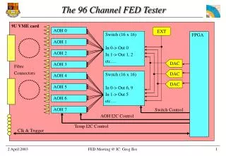
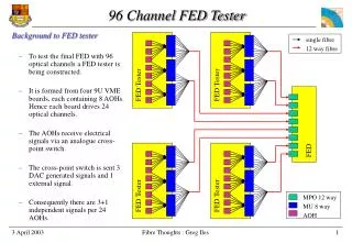
FED Tester. FED Tester. FED Tester. FED Tester. FED. MPO 12 way MU 8 way AOH. single fibre 12 way fibre. 96 Channel FED Tester. Background to FED tester To test the final FED with 96 optical channels a FED tester is being constructed.

E N D
FED Tester FED Tester FED Tester FED Tester FED MPO 12 way MU 8 way AOH single fibre 12 way fibre 96 Channel FED Tester • Background to FED tester • To test the final FED with 96 optical channels a FED tester is being constructed. • It is formed from four 9U VME boards, each containing 8 AOHs. Hence each board drives 24 optical channels. • The AOHs receive electrical signals via an analogue cross-point switch. • The cross-point switch is sent 3 DAC generated signals and 1 external signal. • Consequently there are 3+1 independent signals per 24 AOHs. Fibre Thoughts : Greg Iles
Fibre connections • Fibre connections.. correct me if I’m wrong... • In an adapter, such as the MU-8 way, the fibre from an MU connector is brought into contact with the fibre of an MU connector opposite. • Slight damage is therefore caused to both fibre connectors when making a connection. • The damage causes the signal to be attenuated. • MU connectors are rated to 500 connections. • MPO connectors are rated to 100 connections. • If the signal becomes sufficiently attenuated the connector or cable needs to be replaced. Fibre Thoughts : Greg Iles
The MU connectors attached to the FED Tester will probably not be connected/disconnected. Each FED will need to be plugged in There are 500 FEDs to be tested MPO connectors are rated for 100 connections. Damage done to FED MPO negligible FED tester cables will be damaged and need to be replaced Replace with 8 x 12-way-MU to MPO cables or Replace with 8 x MPO to MPO cables FED Tester FED Tester FED Production Testing = Area to replace or FED Fibre Thoughts : Greg Iles
FED Tester Development testing = Area to replace or repair • A single FED will be examined with all 96 channels driven simultaneously. • Due to the limit of only having 3 independent channels per 9U card we were intending to use the FED tester 8-way connectors like as a patch panel. • If we needed to drive 12 independent channels (e.g. into 1 FED front end module) we could achieve this by taking 3 optical channels from each 9U card and merging them together. • It is unlikely that we will re-wire our patch panel 500 times, but if we were to do this we would damage not only the cables, but also the AOH MU connectors. • Repair 32 AOHs and replace 8 x 12-way-MU-to-MPO fan-in • or • Add an extra MU stage to avoid repairing AOHs. A further MU stage would avoid replacing 12-way-MU-to-MPO fan-in FED or FED Tester FED Fibre Thoughts : Greg Iles
My preferred option Additional MPO-MPO connections ensure that production testing proceeds smoothly It is assumed that we don’t rewire the patch panel more than 500 times. The worst case scenario is that 32 AOHs need their pigtails spliced onto new connectors and we need new 8 MU-to-MPO fan-ins. The ultimate solution The left hand side picture shows the most flexible “throw-away” solution, but also a cabling nightmare. FED Tester Conclusions = Area to replace or repair FED Tester FED FED Fibre Thoughts : Greg Iles
Cross-talk • In CMS • The time difference between signals arriving at the FEDs will be due to different cable lengths and particle time of flight. • In the lab • The time difference between signals arriving at the FEDs will be due to the DAC clocks on the FED tester being delayed. • The consequence is that when these signals pass through the AOH and to a lesser extent the analogue cross-point switch there will be cross-talk. • How serious is this ? Fibre Thoughts : Greg Iles
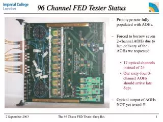
Status • Schematics finished (almost) and design in layout. • Forced into a 2 FPGA solution by lack of I/O • Some minor additions to the schematics needed (e.g import power supply designed by Osman Zorba). • AOH (Optical Hybrid) temperature control system tested • Stable to +/- 0.1 °C. • Can absorb +/- 3 °C changes in lab temperature. • VHDL written to perform PID algorithm in FPGA (untested) • Some potentially long lead time components purchased. Fibre Thoughts : Greg Iles
Artwork Fibre reels Analogue Optical Hybrid (AOH) 8-way MU connectors DACs Clk & Control (e.g. L1A) Cross-point switches Fibre Thoughts : Greg Iles
Why temperature control system Laser output drifts by 1 MIP/°C FED input range = 13 MIPs. APV requires 8+1 MIPs. Hence temperature fluctuations < +/- 2°C. Ideally < +/- 1°C. Temperature Control System Combined DAC/ADC controlled via I2C Temp sensor Brass & perspex provide support and control heat flow Fibre cables AOH Heating resistor Fibre Thoughts : Greg Iles
Temperature Control Performance Temperature stable to 0.2°C (peak to peak) System can at present only respond to +/- 3°C changes Masking tape securing system fails Results from James Leaver Fibre Thoughts : Greg Iles