Download
1 / 96
1.23k likes | 1.88k Views
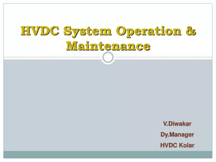
HVDC System Operation & Maintenance. V.Diwakar Dy.Manager HVDC Kolar. Existing HVDC in INDIA. BIPOLE SYSTEMS: RIHAND- DADRI (DELHI) 1500 MW BIPOLE (1991) TALCHER - KOLAR 2500 MW BIPOLE (2001) BALIA - BHIWADI 2500 MW BIPOLE (2010 ) NER –AGRA 6000MW AT +/- 800KV DC ( Proposed)

E N D
HVDC System Operation & Maintenance V.Diwakar Dy.Manager HVDC Kolar
Existing HVDC in INDIA BIPOLE SYSTEMS: RIHAND- DADRI (DELHI) 1500 MW BIPOLE (1991) TALCHER - KOLAR 2500 MW BIPOLE (2001) BALIA - BHIWADI 2500 MW BIPOLE (2010 ) NER –AGRA 6000MW AT +/- 800KV DC ( Proposed) BACK-TO-BACK SYSTEMS: VINDHYACHAL 2 X 250 MW BACK TO BACK(1989)CHANDRAPUR 2 X 500 MW BACK TO BACK(1997)VIZAG 2 X 500 MW BACK TO BACK(1999) SASARAM 1 X 500 MW BACK TO BACK(2002)
Advantages of HVDC • Why HVDC rather than HVAC? • Long distances make HVDC cheaper • Improved link stability • Fault isolation • Asynchronous link • Cable Transmission • Low Right of Way (RoW)
Cost comparison of ac and dc transmission Cost of AC Line Cost Break even distance Cost of DC Line Cost of DC terminal Cost of AC terminal 500 – 700 km Distance in km
Current Current Modes of Operation Bipolar Smoothing Reactor DC OH Line Smoothing Reactor Thyristor Valves Thyristor Valves Converter Transformer Converter Transformer 400 kV AC Bus 400 kV AC Bus AC Filters, Reactors AC Filters
Current Modes of Operation Monopolar Ground Return Smoothing Reactor DC OH Line Smoothing Reactor Thyristor Valves Thyristor Valves Converter Transformer Converter Transformer 400 kV AC Bus 400 kV AC Bus AC Filters, Reactors AC Filters
Current Modes of Operation Monopolar Metallic Return Smoothing Reactor DC OH Line Smoothing Reactor Thyristor Valves Thyristor Valves Converter Transformer Converter Transformer 400 kV AC Bus 400 kV AC Bus AC Filters, Reactors AC Filters
Basic Configuration - HVDC DC TRANSMISSION AC SYSTEM A TERMINAL A TERMINAL B AC SYSTEM B LINE Pd = Vd Id L L I d d d Vd FILTER FILTER
Ideal No-Load Condition 1 3 C A V d B 2
Effect of Control Angle 1 3 u u u C A V d B 2
RECTIFICATION 120 º 180 º 240 º 300 º 60 º 120 º 180 º 0 E . 2 LL E . 2 0.866 LL DC Terminal Voltage
INVERSION E . 2 LL E . 2 0.866 LL 120 º 180 º 240 º 300 º 60 º 120 º 180 º 0 DC Terminal Voltage
HVDC Control • Features • Id in One direction • Magnitude of power is controlled by controlling the voltage difference on the link • Power direction is reversed by reversing the voltage
HVDC EQUIPMENTS What are the Special Components of HVDC?
MAIN COMPONENTS OF HVDC • Converter Transformer • Valve Hall • AC Harmonic Filters • Shunt Capacitors • DC Harmonic Filters • Smoothing Reactors • DC Current / Voltage measuring devices • Valve Cooling / Ventilation System
Basic Components of HVDC Terminal Converter Xmers DC Line Smoothing Reactor AC Harmonic filters 400 kV DC Filter Electrode station AC Shunt Capacitors Valve Hall -Thyristors Valve Cooling / Ventilation system -Control & Protection -Telecommunication
CONVERTER TRANSFORMER 400KV SIDE BUSHING STAR BUSHINGS DELTA BUSHING
CONVERTER TRANSFORMERS • Three Singe Phase Transformers for each Pole • Each Transformer is of Three Windings • Winding -1 connected to 400KV side in Star • Winding -2 connected to one six pulse bridge in Star • Winding -3 connected to second six pulse bridge in Delta • Easy transportation
FEATURES OF CONVERTER TRANSFORMERS • Automatic onload tap changer control with appropriate make and break capacity • Extra insulation due to DC currents • Proper conductors and magnetic shunts to take care of the extra losses due to harmonic currents • Very rugged and reliable OLTC as tap-changing is a integral means of conversion process and control.
Converter Transformer Ratings • Type of converter transformer : Single phase three windings • Rated power of line / star / delta winding (MVA) : 397/198.5/198.5 • Rated current of line / star / delta winding (A):1719/1635/944 • Rated Voltage of Line/star/delta winding (No-load):400/√3/210.3/√3/210.3 • Tap changer (voltage range) : -5 % to +20 % • Tap changer steps : 16 to -4 (21 steps) • Tap changer current capacity: 2X2000A • Cooling arrangement : ODAF
Converter Transformer Ratings • No load losses – 192KW • Load losses - 760KW @75°C • Oil type – Napthanic, Shell Diala • Bushings • Line side – oil filled • Valve side – Y – SF6 filled • Valve side – D – RIP condenser • Total weight – 461 Ton • Oil weight – 118.7 Ton
Converter Transformer Connection Valve Hall 1-ph 3 winding Converter Transformer D R Y D Y Y D B Y Outdoor
Converter Transformer Cooling control • Automatic daily changeover of cooling pumps and fans • 5 groups of fans and pumps • Each group – One oil circulating pump & 3 cooling fans • 4 groups will be in service with 2 fans each • One redundant group – changeovers every day • Extra fans will switch ON when winding temperature > 75ºC • Redundant group will switch ON when winding temperature >85ºC • WTI Alarm - 115ºC • WTI Trip - 130ºC • OTI Alarm - 85ºC • OTI Trip - 95ºC
MULTIPLE VALVE UNIT Multiple Valve Unit D Y Y
1. AC Terminal 2. DC Terminal 3. Cooling Water Inlet 4. Cooling Water Outlet 5. Fiber Optic Cables Tubes 6. Thyristor Module 7. Insulator 8. Arrester 9. Screen Valve Tower side view • Max. length of fibre optic cables in quadruple valve Lmax = 17.5m • Weight of quadruple valve without arresters: approx. 19300 kg • All dimensions in mm
Valve Structure Valve Section / tier Single Valve Quadra Valve
Hierarchy of valve structure • Each Thyristor level consists • Thyristor • Snubber circuit – to prevent high dv/dt • Snubber Capacitor • Snubber Resistor • Valve Reactor – to prevent high di/dt • Grading Resistor – to equilize the potential across all the levels in a valve – static equalizing • Grading capacitor – dynamic equalizing
Thyristor Module GRADING CAPACITOR SNUBBER CAPACITOR SNUBBER RESISTOR COOLING PIPE-PEX THYRISTOR TE CARD FIBRE OPTICS
1 Light Receiver 2 Light Transmitter 3 Thyristor Voltage Detection 4 Logic 5 Gate Pusle Amplifier 6 Back Up Trigger Circuit (BTC) 7 Energy Supply Block Diagram of Thyristor Electronic
Thyristor T1501 N75 T - S34 (1) • Features: • High-power thyristor for phase control • Ceramic insulation • Contacts copper, nickel plated • Anode, Cathode and gate pressure contacted • Inter digitised amplifying gate • Applications: • HVDC-Transmissions • Synchro- drivers • Reactive-power compensation • Controlled Rectifiers
Valve Reactor - Electrical and Mechanical Ratings • Voltage-time area = 80mVs ±10% • Saturated part of main inductance LH = 0.55 mH ±10% • Reactor current ID max = 1270 A Current and Voltage Characteristic of the Valve Reactor
Grading Capacitor - Electrical and Mechanical Ratings • Capacity C = 2.4 µF ±3% • Nominal voltage UN = 58 kV • Periodical max. voltage Umax = 88 kV • Short time max. impulse voltage Us = 8700 V • Nominal effective current IN = 1 A • Periodical max. current Imax = 100 A • Operating frequency f = 50/60 Hz • Cooling type self-cooling • Weight approx. 25 kg • Impregnation SF6 gas
Snubber Circuit Resistor Resistance R 45 Tolerance ± 3% Cooling Water
Snubber Circuit Capacitor X View X Capacitance 1.6 µFd Tolerance +/-5% Insulation SF6