StoneBeat Authorized Training Program
StoneBeat Authorized Training Program. StoneBeat™ 3.1 TRAINING WELCOME! Firstname Lastname Companyname first.lastname@company.name. StoneBeat 3.1 Training. DAY 1: Unit 1 - Overview Unit 2 - Sample Configurations Unit 4 - Planning the Installation


StoneBeat Authorized Training Program
E N D
Presentation Transcript
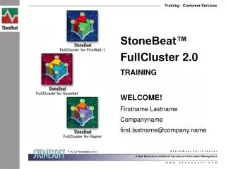
StoneBeat™ 3.1 TRAINING WELCOME! Firstname Lastname Companyname first.lastname@company.name
StoneBeat 3.1 Training • DAY 1: • Unit 1 - Overview • Unit 2 - Sample Configurations • Unit 4 - Planning the Installation • Unit 5 - Installation and Configuration on UNIX (Solaris) • Unit 6 - Installation and Configuration on Windows NT • Lab 9: Installation and Configuration on UNIX (Solaris) • Lab 10: Installation and Configuration on Windows NT
StoneBeat 3.1 Training • DAY 2: • Unit 3 - Administration • Lab 7: StoneBeat GUI • Lab 8: The Swithover • Lab 11: Test Subsystem • Lab 12: Load Sharing Configuration • Training Review • Certification Exam
StoneBeat Administration Unit 1: Overview • StoneBeat Philosophy • StoneBeat Features • StoneBeat Facts • Terminology • Software Components • Operating Principles • Hot Standby • Load Sharing • The Switch-over
External network Primary Secondary Internal network StoneBeat... • is a High Availability firewall system which is designed and optimized for FireWall1™ of Check Point Software Technologies.
Primary Secondary StoneBeat Philosophy • The idea of High Availability is to avoid single point of failures in the system. • The most critical component is the firewall node itself. • In the StoneBeat system there are two firewall nodes.
StoneBeat Features • StoneBeat detects hardware and software failures and • … manages a fast and transparent switch-over to the secondary system in case of failure in the primary. • StoneBeat supports hot standby and • … load sharing configurations. • A hot standby solution enables firewall software and hardware maintenance during normal business hours.
StoneBeat Features • The load sharing option enables an active role for both firewalls and fulfills even the highest requirements for firewall throughput.
Terminology Firewall Node • is a gateway machine running a FireWall-1 Module and StoneBeat Module StoneBeat HA Unit • is a pair of firewall nodes, which can share load and back each other up. The two firewalls are called Primary and Secondary. StoneBeat Cluster • consists of two or more StoneBeat HA Units Stonebeat Site • can be either a StoneBeat Cluster or a single StoneBeat HA Unit.
Terminology Primary and Secondary • are identical systems that both have the same network connections • both run test subsystems that monitor the operating systems, network interfaces and FireWall-1 operation and are fully configurable In hot standby configurations • the primary is normally online and performing the tasks of a firewall. The secondary is in standby state, continuously testing the functionality of the primary using a heartbeat protocol.
Terminology • In case the primary itself (or the secondary) recognizes any problems in the primary, the site will go to a failover state where the secondary handles the tasks of firewall and puts the primary in an offline state.
Terminology In load sharing configurations • both primary and secondary firewalls are active in the normal state. In case of a failure on one firewall node, the other node takes the tasks of the failed node to itself and puts it in an offline state. NOTE: In both types of configurations, a site in a failover state requires manual interaction to switch back to the normal state.
External ONICs Primary Secondary Internal ONICs Terminology ONIC - Operative Network Interface Card • Interfaces used to handle normal operative traffic. • Connects the firewalls themselves to internal, external and DMZ networks. • When a firewall is in online state, all ONICs are up. • When it is in offline state, all ONICs are down. • ONICs connected to the same network have exactly the same IP and MAC addresses • StoneBeat configures and controls all ONIC’s.
Primary ONIC Secondary ONIC Primary Secondary Primary ONIC Secondary ONIC Terminology ONIC Groups • In load sharing configurations ONICs are divided into two interface groups: primary and secondary. • The interfaces in different groups have different IP and MAC addresses. • When sharing load, the ONICs of the primary group are up on the primary firewall and the ONICs of the secondary group on the secondary firewall. • In hot standby configurations all ONICs are primary ONICs.
Primary Secondary CNICs Terminology CNIC - Control Network Interface Card • Dedicated to communications between primary and secondary firewalls and the management system. • StoneBeat does not control these interfaces, they are are always up, regardless of the state of the system. The number of CNICs depends on the system’s configuration: 1. You may have two heartbeat links that are both LANs. In this case you have two CNICs per firewall. 2. Alternatively you may use a serial link as a second heartbeat and in this case you have one CNIC per firewall.
Primary Secondary ID CNICs Terminology ID CNIC • The CNIC which has the IP address of the firewall’s hostname is called identity CNIC or simply ID CNIC. • The IP address of ID CNIC is used by management systems to communicate with the firewall.
HUB Heartbeat link 1 Primary Secondary HUB Heartbeat link 0 Terminology Heartbeat • Connection between StoneBeat modules. Used to pass commands and state information between the firewalls. The Default link is established between ID CNICs. StoneBeat Module • StoneBeat software component running on the firewall that implements the heartbeat protocol and takes care of actions needed by the switch-over procedure. • Also used to coordinate manually activated switch-overs.
Terminology Test Subsystem • Runs on both firewalls to detect hardware and software failures • Can be used to monitor the operating system, network interfaces and FireWall-1 operation. • Depending on the configuration, the test subsystem will generate alerts or activate the switch over if a test program fails. • Is completely configurable: any shell command can be run as a test.
External network • Firewall module • StoneBeat module • SNMP agent • Firewall module • StoneBeat module • SNMP agent Primary Secondary • Firewall control • StoneBeat control Control Internal network Software Components
Primary Secondary Control Software Components: sbd StoneBeat module (sbd) • Runs on primary and secondary firewalls. • Implements the heartbeat protocol. • Also implements the test subsystem which runs on the secondary firewall. This is used to monitor packet flow trough the primary firewall and to activate the switchover procedure if the primary firewall fails. External network sbd sbd Heartbeat Internal network
Primary Secondary Control Software Components: SNMP StoneBeat SNMP agent • can co-exist with other SNMP agents. • provides the status of the StoneBeat site to standard network management systems. • SNMP trap can be used to send alerts to a network management system External network SNMP SNMP SNMP trap Internal network
1. StoneBeat Management GUI 2. StoneBeat Command Line Interface (sbcontrol) 3. Check Point FireWall-1 Management Server 4. Check Point FireWall-1 GUI Management software can be installed by Client/Server model or all modules can be installed into a single workstation. NOTE: All Communication between sbcontrol and sbd is protected against network eavesdropping by one time passwords. Primary Secondary Control Software Components: Management System A full management system includes the following software modules: External network sbcontrol sbcontrol GUI sbcontrol Internal network
1.The GUI polls each preconfigured site every few seconds. Site configuration and status information are displayed in the site monitor view. 2. The GUI can be used to send control commands to a StoneBeat site. Software Components: GUI The StoneBeat Management GUI enables management of StoneBeat sites from your desktop. It has two main functions:
RS-232 Primary Secondary Control System Components: UPS A UPS has two functions in StoneBeat: 1. Supply high quality and uninterruptible power to the primary firewall 2. Provide a method for the secondary firewall to do an emergency shutdown of the primary firewall in case of severe failure. • The UPS is controlled through a serial line from the secondary firewall. External network Internal network
External network Primary Secondary Online Offline Internal network Operating Principle: Hot Standby Asymmetric hot standby • Only one gateway is active at any given time -> no load sharing • Automatic switchover only from primary to secondary • Identical IP and MAC addresses for ONICs • ONICs are DOWN on the offline gateway
External network Primary Secondary Internal network Operating Principle: Hot Standby • One additional interface is required on both firewalls for heartbeat and management • Optionally another additional interface or serial line can be used to duplicate the heartbeat
External network sbcontrol sbcontrol Primary Secondary GUI GUI Control sbcontrol Internal network Operating Principle: Hot Standby • The FireWall-1 GUI and StoneBeat GUI can be installed on the control workstation and/or on an administrator’s workstation (recommended) • StoneBeat command line interface (sbcontrol) can be used on the gateways themselves and also on additional control workstations.
Operating Principle: Hot Standby The heartbeat and control protocols are strictly authenticated using a challenge-response method that is based on strong cryptographic one-way functions. NOTE: The Management System communicates with each managed firewall by using the IP address of the firewall’s identity CNIC (ID CNIC).
Firewall Node Firewall Node 10.0.0.1 192.168.0.1 Internal Network 10.0.0.2 External Network 192.168.0.2 10.0.0.1 192.168.0.1 10.0.0.2 192.168.0.2 Operating Principle: Load Sharing • StoneBeat enables load sharing between the nodes of HA Unit. • Requires two interfaces to the same subnetwork with distinct IP addresses. • Load sharing is accomplished by means of static routing. • Special care must be taken to avoid asymmetric routing.
Firewall Node Firewall Node Firewall Node Firewall Node Firewall Node Firewall Node Operating Principle: Load Sharing • StoneBeat scales up by using two or more HA Units in parallel. Internal Network External Network Gigabit Ethernet Fast Ethernet
Primary Secondary Operating Principle: Switch-over During switch-over the firewall node reconfigures its ONICs to use the same IP and MAC addresses that the other firewall had. The user only sees a delay of a few seconds.
Operating Principle: Switch-over The switch-over... calls a function that installs all static routes into the operating system kernel immediately after reconfiguration. is synchronized between nodes so that the firewalls are never connected to the network using the same IP and MAC addresses at the same time. is completetely transparent to other devices so it is unnecessary to propagate any routing changes to next hop routers. can be customized to execute commands executed either synchronously during different phases of the switch-over or asynchronously after.
Operating Principle: Switch-over Real world switch-over cases include: 1. System disk failure on the primary firewall. 2. Ethernet NIC failure on the primary firewall. 3. Operating system crash on the primary firewall. 4. Accidental human error that caused a power failure on the primary firewall. 5. Configuration error made by non expert system manager on the primary firewall. 6. Discussion Topic
Operating Principle: Switch-over The successful switch-over of existing user connections depends on: 1. FireWall-1 Synchronization 2. TCP/IP protocol of the connection 3. FireWall-1 NAT rules in use 4. FireWall-1 VPN and SecuRemote usage 5. FireWall-1 version
Operating Principle: Switch-over By basic principle, StoneBeat will not try to automatically switch back to the failed firewall. Discussion Topic
Unit 1 - Summary • What is StoneBeat? • What does it do? • What doesn’t it do? • Can you describe • a hot standby configuration? • a load sharing configuration? • the switch-over procedure? • What software components are involved? • Understanding and using the correct terminology is important.
StoneBeat Administration • Unit 2: Sample Configurations • Control in Internal Network (Windows NT GUI) • Dedicated Control Network (Windows NT GUI) • Dedicated Control Network with Load Sharing(Windows NT GUI) • Dedicated Control Network with Load Sharing(Unix config files) • Load Sharing Discussion
External Network Primary Secondary External Router 10.1.1.2 Internal Network Control External HUB 10.1.1.1 10.1.1.1 COM 10.0.1.1 .11 .12 10.0.1.1 Internal HUB Management Server 10.0.1.10 GUI Clients Sample Configuration:Control in Internal Network • The FireWall-1 GUI Client communicates with the Management Server and the Server communicates with the primary and secondary firewalls. • The StoneBeat GUI communicates directly with the primary and secondary firewalls. Both management systems should be configured to communicate with firewalls using the IP address of the control interfaces CNICs.
Sample Configuration:Control in Internal Network - Sites • In the Network structure drop down list, Control through Internal Network is selected. • The IP address and the address of the heartbeat link 0 is the address of the ID CNIC. • Duplicated heartbeat is configured to use the COM3 serial port on both ends.
Sample Configuration:Control in Internal Network - Interfaces • Three interfaces are configured: one CNIC and two Primary ONICs. • The MAC addresses of the ONICs on the primary firewall match the MAC addresses of the corresponding ONICs on the secondary firewall. • The MAC address of the control interface is empty to use the hardware default.
Sample Configuration:Control in Internal Network - Routes • In online state, the default gateway of both firewalls is the external router. • In offline state, the default gateway of the primary firewall is the secondary firewall. • In offline state, the default gateway of the secondary firewall is the primary firewall.
Sample Configuration:Control in Internal Network - Routes • In online state, both hosts are connected to the internal network using their ONICs. • In offline state, the primary firewall is connected to the internal network using its CNIC. • In offline state, the secondary firewall is connected to the internal network using its CNIC. • In online state, both hosts are connected to the external network using their ONICs. • The primary firewall communicates with the secondary always directly using its CNIC. • The secondary firewall communicates with the primary always directly using its CNIC.
External Network External Router 10.1.1.2 External HUB 10.1.1.1 10.1.1.1 COM 192.98.99.42 Primary Secondary 10.0.1.1 .41 10.0.1.1 Control HUB Internal HUB Management Server Internal Router GUI Client Internal Network Control GUI Clients in Internal Network Sample Configuration:Dedicated Control Network • The FireWall-1 Management server is located in a dedicated control LAN which is directly connected to the firewalls. • The FireWall-1 GUI Client software and StoneBeat Management GUI should installed either in the Management Server Workstation or into a separate GUI Client workstation.
Sample Configuration:Dedicated Control Network - Site • In the Network structure drop down list, Dedicated Control Network is selected. • The IP address and the address of the heartbeat link 0 is the address of the ID CNIC. • Duplicated heartbeat is configured to use the COM3 serial port on both ends.
Sample Configuration:Dedicated Control Network - Interfaces • In the Interfaces tab, three interfaces are configured: one CNIC and two Primary ONICs. • The MAC addresses of the ONICs on the primary firewall match the MAC addresses of the corresponding ONICs on the secondary firewall. • The MAC address of the control interface is empty to use the hardware default.
Sample Configuration:Dedicated Control Network - Routes • In online state, the default gateway of both firewalls is the external router. • In offline state, the default gateway of the primary firewall is the secondary firewall. • In offline state, the default gateway of the secondary firewall is the primary firewall. • In online state, both hosts are connected to the internal network using their ONICs. • In online state, both hosts are connected to the external network using their ONICs.
External Network External Router 10.1.4.2 External HUB 10.1.4.1 .129 .1 10.1.4.129 Primary Secondary 192.98.99.48 10.0.4.1 .47 .1 10.0.4.129 Control HUB Internal HUB Management Server GUI Client Internal Network Control GUI Clients in Internal Network Sample Configuration: Dedicated Control Network with Load Sharing • In this load sharing configuration, two distinct gateway IP addresses are used. The load sharing between these gateways is also configured in the external router in order to avoid asymmetric routing. • The FireWall-1 Management server is located in a dedicated control LAN which is directly connected to the firewalls.