Download
1 / 42
420 likes | 596 Views
Optimizing the Architecture of SFQ-RDP (Single Flux Quantum- Reconfigurable Datapath). F. Mehdipour *, Hiroaki Honda ** , H. Kataoka*, K. Inoue* and K. Murakami* *Graduate School of Information Science and Electrical Engineering, Kyushu University, Japan

E N D
Optimizing the Architecture of SFQ-RDP (Single Flux Quantum- Reconfigurable Datapath) F. Mehdipour*, Hiroaki Honda**, H. Kataoka*, K. Inoue* and K. Murakami* *Graduate School of Information Science and Electrical Engineering, Kyushu University, Japan **Institute of Systems, Information Technologies and Nanotechnologies (ISIT), Fukuoka, Japan E-mail: farhad@c.csce.kyushu-ua.c.jp
CREST-JST (2006~): Low-power,high-performance, reconfigurable processor using single-flux quantum circuits Superconducting Research Lab. (SRL) SFQ process Yokohama National Univ. SFQ-FPU chip, cell library Nagoya Univ. SFQ-RDP chip, cell library, and wiring Nagoya Univ. CAD for logic design and arithmetic circuits Dr. S. Nagasawa et al. Prof. N. Yoshikawa et al. Prof. A. Fujimaki et al. Prof. N. Takagi (Leader) et al. Kyushu Univ. Architecture, Compiler and Applications Prof. K. Murakami Dr. K. Inoue Dr. H. Honda Dr. F. Mehdipour H. Kataoka SFQ-LSRDP
Agenda • Introduction • Large-Scale Reconfigurable Data-Path(LSRDP) General Architecture and Specifications • Design Procedure and Tool Chain • Preliminary Results • Conclusions and Future Work
Introduction NVIDIA Tesla S1070 http://www.nvidia.com • For performance improvement various accelerators are used with GPPs • PowerXcell, GPU, GRAPE-DR, ClearSpeed, etc. • Small size and low power consumption comparing to processors with similar performance
Acceleration Through a Data-Path Processor • Mechanism • Acceleration by using a data-path accelerator • Augmenting the accelerator to the base processor • Executes hot portions of applications on the accelerator
How a Reconfigurable Processor Works Non-critical code GPP critical code LSRDP Non-critical code critical code Non-critical code . . . Application code Main Memory
Processor Coprocessor RFU Memory Bridge Attached Processor Coupling an Accelerator to a Processor Tight Coupling Tight Coupling Loose Coupling
Motivation • Large-Scale Reconfigurable Data-Path (LSRDP): • is introduced as an alternative accelerator • reduces the no. of memory accesses by utilizing data-path Conventional accelerators: • A large memory bandwidth is demanded in conventional accelerators for high-performance computation • On chip memories are often used to hide memory access latency
Outline of Large-Scale Reconfigurable Data-Path (LSRDP) processor • Features: • Data Flow Graphs (DFGs) extracted from critical calculation parts are directly mapped • Pipeline execution • Burst transfer is used for input /output rearranged data from/to memory • Reconfigurable data-path includes: • A large number of floating point Functional Units (FUs)Arranged as arrays • Reconfigurable Operand Routing Network : (ORN) • Dynamic reconfiguration facilities • Streaming Buffer (SB) for I/O ports LSRDP GPP ... FU FU FU FU ORN : Operand Routing Network : : : : ... FU FU FU FU ORN ... FU FU FU FU SB SMAC Main Memory Scratchpad Memory
Single-Flux Quantum (SFQ)against CMOS • CMOS issues: (if LSRDP has 32x32 FUs) • high electric power consumption • high heat radiation and difficulties in high-density packing • SFQ Features: • High-speed switching and signal transmission • Low power consumption • Compact implementation of a system (small area) • No cost for latch • Suitable for pipeline processing of data stream • Serial bit-level processing
Goals of the Project Designing and Implementing SFQ-LSRDP architecture considering the features and limitations of SFQ circuits Discovering appropriatescientific applications Developing compiler tools Developing performance analyzing tools
Parameters Should Be DecidedWithin the LSRDP Design Procedure • Core structure: a rectangular matrix of PEs • PE: combination of a Functional Unit (FU) • and a data Transfer Unit (TU) Width and Height ? Maximum Connection Length (MCL) between consecutive rows? (impossible to implement full cross bar) Layout: FU types (ADD/SUB and MUL)? Reconfiguration mechanism? (PE, ORN, Immediate data) • On-chip memory configuration?
LSRDP Architecture • Processing Elements • FU • implements basic 64-bit double-precision floating point operations including: ADD, SUB and MUL • TU (transfer unit) as a routing resource for transferring datafrom a row to an inconsecutive row FU FU FU TU FU TU FU TU TU TU PE including Two components Four functionalities
W … … … … ORN A A A A A A A A A A A A A A A A A A A A T T T T T T T T T T T T T T T T T T T T ADD/SUB TU ORN M M M M M M M M M M M M M M M M M M M M MUL . . . ORN Layout Types- Type I Each PE implements ADD/SUB and MUL H M : MUL A : ADD/SUB T : Transfer Unit Flexible but consume a lot of resources
W A A A M M M A A A M A M A A A M M A A M T T T T T T T T T T T T T T T T T T T T … … … … ORN ADD/SUB TU ORN MUL TU . . . ORN Layout Types- Type II (Checkered) Each PE implements ADD/SUB or MUL Each PE implements ADD/SUB or MUL H
W M M M M M A A A A M M A A A A A M M M A T T T T T T T T T T T T T T T T T T T T … … … … ORN ADD/SUB TU ORN MUL TU . . . ORN Layout Types- Type III (Striped) Each PE implements ADD/SUB or MUL Each PE implements ADD/SUB or MUL H Type II or III, which one is more efficient?
Maximum Connection Length (MCL) MCL:maximum horizontal distance between two PEs located in two subsequent rows
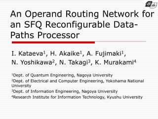
An ORN Structure ORN 2bit shiftregister ORN is consisted of2-bit shift registers, 1-by-2 and2-by-2 cross bar switches A. Fujimaki, et al., Demonstration of an SFQ-Based Accelerator Prototype for a High-Performance Computer,” ASC08, 2008.
Dynamic Reconfiguration Architecture • Three bit-stream lines for dynamic reconfiguration of: • Immediate registers (64bit) in each PE • Selector bits for muxes selecting the input data of FUs • Cross-bar switches in ORNs
Compiler and Design Flow • DFGs are manually generated from critical parts of applications • DFG mapping results are used for • Analyzing LSRDP architecture statistics • Generating LSRDP configuration bit-streams
Benchmark Applicationsfor Design Procedures • Finite differential method calculation of2nd order partial differential equations • 1dim-Heat equation(Heat) • 1dim-Vibration equation (Vibration) • 2dim-Poisson equation (Poisson) • Quantum chemistry application • Recursive parts of Electron Repulsion Integral calculation(ERI-Rec) Only ADD/SUB and MUL operations are usedin the critical calculations of all above applications
DFG Extraction- Heat Equation • 1-dim. heat equation for T(x,t) • Calculation by Finite DifferenceMethod (FDM) (A is const.) Basic DFG can be extended to horizontal and vertical directions to make a larger DFG Basic DFG corresponding to minimum FDM calculation
Example of extracted DFGs- Heat Inputs: 32 Outputs: 16 Operations: 721 Immediates: 364 A huge sample DFG (Heat)
DFG Distribution for each application ERI-Rec (8 DFGs) Vibration (7) 24DFGs # of FUs Heat (6) Poisson (3) # of Inputs DFGs have different qualities in terms of the # of FUs, # of Inputs and Outputs
DFG Classification Totally, 24 DFGs are prepared for benchmark Apps. Due to broad range of DFG sizes DFGs are classified as S, M, L, XL with respect to their size and the number of Input/Output nodes => LSRDP designing processes for S, M, L, XL, respectively
Mapping DFGs onto LSRDP Longest connections
LSRDP Design Procedure DFGs & LSRDP HW constraints For each parameter Appropriate values for all parameters
LSRDP Specifications: Width & Height LSRDP Dimensions and the number of input/output ports
LSRDP Specifications: MCL Further MCL optimization needed
Analyzing Various LSRDP Layouts (Except ERI1 DFG which gives better size for Layout III) Layout II can be used instead of Layout I to obtain a smaller LSRDP
Preliminary Performance Evaluation Base processor configuration GPP+LSRDP configuration GPP: Exec. time measurement by means of a processor simulator LSRDP: Estimation by performance modeling
Preliminary Performance Evaluation(Heat) Basic: SB only Reuse: SB + SPM Data reusing is employed to avoid the need for data rearrangement as well as frequently data retrieval from the scratchpad memory.
Preliminary Performance Evaluation (Poisson) A small fraction is related to processing time on LSRDP and the main fraction concerns to various overhead times as well as the execution time on GPP
Conclusions & Future Work • A high-performance computer comprising an accelerator (LSRDP) implemented by superconducting circuits was introduced. • 24 benchmark Data Flow Graphs (DFGs) were manually generated. • LSRDP micro-architecture is designed based on characteristics of scientific applications via a quantitative approach. • LSRDP is promising for resolving issues originated from CMOS technology as well as achieving considerable performances. • Future Work: • To achieve higher performance it is required to reduce various overhead costs mainly related to data management part. • To reduce the implementation cost of LSRDP, we will focus on reducing maximum connection length and ORN size.
Acknowledgement This research was supportedin part by Core Research for Evolutional Scienceand Technology (CREST) of Japan Scienceand Technology Corporation (JST).
2x3 RDP processor prototype • 8-bit ALUs implementing: • ADD, SUB, AND, OR, XOR • 25GHz Frequency • 6-bit Data transfer shift registers • 16-bit I/O shift registers • 21 Pipeline stages • 7-bit Data width • Area:6.84 x 6.72 mm2 • Total number of Junctions:14040JJs • Bias current: 1.652A Fujimaki, et al., Demonstration of an SFQ-Based Accelerator Prototype for a High-Performance Computer,” ASC08, 2008