
Innovative Helical Phaser for Hollow Camshafts
E N D
Presentation Transcript
Variable Valve Timing Device Unique Design to Operate Inside a “Constructed” or Hollow Camshaft
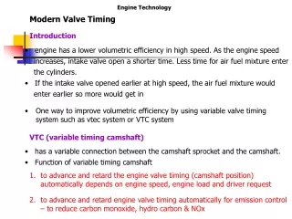
Existing Technology • Existing Variable Valve Timing systems employ a vane-type device that is quite heavy, complex, and is typically mounted on the front end of the camshaft, aligned with the plane of the cam sprocket and drive chain. • This device also has very short stroke, in terms of the arc distance from fully retarded to fully advanced positions. This results in less-than optimal precision in cam position control.
Alternative Possible when Hollow Camshafts are Utilized • When “constructed” hollow camshafts are utilized, and the ID of the shaft is approximately 19 mm, the KayMor Helical Phaser can be utilized. This entire device can be enclosed inside the camshaft. Its design does not depend on the maintenance of oil pressure to support the torque loads of the camshaft. Positioning can be accomplished by either ported oil or electrically.
Options for Positioning • The initial design was intended to utilize the same pressurized oil that operates the typical vane-type device. Porting would be changed to deliver the oil to the inside of the camshaft on either end of the “piston,” analogous to the delivery to either side of the vanes. The same valve and controller could be utilized as is use for the vane-type devices.
Since the position does no depend on the maintenance of oil pressurized to engine oil pressure levels, relatively little oil is required. • This fact also allows the electrical positioning using either a linear motor or, if greater precision is desired, a servo with screw.
Illustrations • The following slides show the concept, using animations. To open, double click on the avi icon.
Option 1 • This option would be utilized when a device is used for each camshaft being controlled. • The option is shown with a single sprocket.
Option 2 • This option shows a configuration that would allow a single device in one camshaft to control the position of two (or more) camshafts. • The configuration is shown with two sprockets, one the “drive” that powers the shaft containing the VVT device, the other to drive the second camshaft.
Potential • If any of Ford’s engines are utilizing “constructed” camshafts, and id the ID is about 19 mm, the KayMor Cam Phaser could replace the existing vane-type unit, reducing weight by about 75%, providing more precise cam position control, allow electrical operation of the device, and at a cost we estimate less that 75% of the cost of the vane-type VVT device.
Moretz Technologies, LLC • 807 Airport Road P. O. Box 4031 Jackson, MI 49204 • 517-780-4002 M 517-206-3287 FAX 517-780-0950 • rdale@moretz.com • Moretz Technologies is in the process of becoming certified as a veteran-owned business.