Download
1 / 12
120 likes | 147 Views
This document discusses the specifications and considerations for the Sensor Actuator Manager (SAM) Controller. It covers its functionality, installation requirements, integration with other systems, diagnostic capabilities, and benefits for process improvement.

E N D
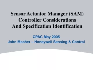
Sensor Actuator Manager (SAM) Controller Considerations And Specification Identification CPAC May 2005 John Mosher – Honeywell Sensing & Control
SAM Controller Requirements • Automatically controls and monitors flow stream conditions (P,T,F) through sensors and actuators on the NESSI substrate • Controls a minimum of 2 Foundation Fieldbus Channels • Installs in hazardous locations (Zone 1; Class 1, Div 2) • Local & Remote Display of status • Plant level access to and control of all system data via OPC • Storage and download of configuration data • Easy programming of control functions & operation • Easy Installation • Supports integration of analyzer information (control and measurement data) • Monitors device diagnostic information • Provides diagnostics on impending faults (low flow or pressure, leak detection) • Wireless Connectivity to Local Handheld and Remote Network.
SAM Offers Opportunities for Process Improvement Feature Benefit • Automatic Device Configuration • Automatic Device Addressing • Automatic Device Settings • Initiation of Cal cycles • Logging of Cal result • Early detection and analysis of flow problems • Plugging • Filter plugging • Leaks • Condensation • Automated shut down control • Initiate line purges on fault • Shut down flow to instrumentation • Automatic Device Configuration • Faster setup • Faster repair • Lower Maintenance cost • Improved process performance • Early detection and analysis of flow problems • Prevent down time losses • Reduced time to diagnose and repair • Personnel Safety • Automated shut down control • Protect equipment and instrumentation
FF1 SensorActuatorManager V A P T SAM Functionality – Where Does it Live? • Three Scenarios for SAM Functional Locations Based on: • Application Environment • Control Strategy • Individual Choice At-Line Sample Point Field - Level 2 LAN (Wired or Wireless) ANLAN Wireless Handheld HMI Class 1 Div 2 Gas Analyzer Sample System NeSSI Generation 2/3 Class 1 Div 1
V A P T Gas Analyzer Sample System NeSSI Generation 2/3 Class 1 Div 1 Scenario 1: Lab Environment • Hazardous Rating not required • PC in use nearby already and capable of all SAM Functionality • Analyzer may have Serial or Ethernet Connection or be PC-Based • MicroAnalytical Device may have own Controller/PC Card • Control of NeSSI best on PC • PC Card for Fieldbus • Frequent Changes to Setup uAnalytical Controller Fieldbus Gas Analyzer
V A P T Scenario 2: Industrial with SAM Control • SAM is a microPC-type Controller • Control and Configuration Data Reside in SAM • Program Downloaded from PC • Reports Status and Sample System Values • Relays Data to ANLAN/DCS/Analyzer GC Wireless Handheld HMI Fieldbus SAM PROCESS CONTROL DOMAIN (DCS) Sample System NeSSI Generation 2/3 Class 1 Div 2 Class 1 Div 1
V A P T Scenario 3: Industrial with FF Control • SAM is a Gateway Device Only • Sample System Programmed and Configured from the PC • Control Runs on the Foundation Fieldbus Net • SAM Reports Status and Sample System Values • SAM Relays Data to ANLAN/DCS/Analyzer GC Wireless Handheld HMI Fieldbus SAM Controller PROCESS CONTROL DOMAIN (DCS) Sample System NeSSI Generation 2/3 Class 1 Div 2 Class 1 Div 1
V A P T The Future: IS uAnalytical System • SAM is a Gateway Device Only • Analytical System Programmed and Configured from the PC • Control Runs on the Foundation Fieldbus Net • SAM Reports Analysis, Status and System Values • SAM Relays Data to ANLAN/DCS Wireless Handheld HMI Fieldbus SAM Gateway uGC PROCESS CONTROL DOMAIN (DCS) Sample System NeSSI Generation 2/3 Class 1 Div 2 Class 1 Div 1
Real Time Clock Power Supply CPU Battery Backup User PDA RF Radio Ethernet Serial Port IS FF H1 Foundation Fieldbus Ch 1 barrier Galvanic Non-Volatile Memory Isolation IS FF H1 barrier G Foundation Fieldbus Ch 2 Galvanic Isolation SAM Controller Electronics Block Diagram
User Interface Sensor Data FF HI Configuration Acquisition data Alarm Monitoring Sensor Measurement data Logic & Sequence Control Data Base Manager & Execution Sequencer Sensor Diagnostic data PID Control Wireless Wireless Diagnostic Serial Bus Comms Stack Monitoring and Driver Preventive / Predictive Comms Server Functions Ethernet Ethernet Serial Bus Comms Stack Driver Data Storage SAM Controller SAM Software Architecture
The Result: Configuration Easy Setup and Startup Sensors, Valves, Filters Control Real-time Sample System Control Connectivity Connect to LAN, Analyzer or Other Higher-Level Systems PID Loops, Flow Rates, Pressure Confidence! Full Diagnostics and Reporting Capability Ethernet, Serial, Discrete and/or Analog I/O to Analyzers or DCS
www.honeywell.com Thanks! John Mosher, Honeywell Sensing & Control (209) 339-4004 John.mosher@honeywell.com