Download
1 / 13
140 likes | 284 Views
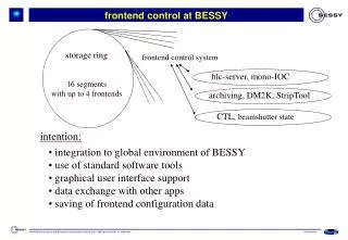
Diagnostics and Optimization Procedures for Beamline Control at BESSY. A. Balzer, P. Bischoff, R. Follath, D. Herrendörfer, G. Reichardt, P. Stange. PC. EPICS-IOC. PLC. EPICS-IOC. PC. EPICS-IOC. PLC. PC. BESSY Beamlines. BESSY Beamline UE112. Insertion Device (ID).

E N D
Diagnostics and Optimization Procedures for Beamline Control at BESSY A. Balzer, P. Bischoff, R. Follath, D. Herrendörfer, G. Reichardt, P. Stange
PC EPICS-IOC PLC EPICS-IOC PC EPICS-IOC PLC PC BESSYBeamlines BESSY Beamline UE112 Insertion Device (ID) Switching Mirror Unit (SMU) 1 Plane Grating Monochromator (PGM) 1 Experimental Chamber PGM 1 Plane Grating Monochromator (PGM) 2 Switching Mirror Unit (SMU) 2 Experimental Chamber PGM 2a Experimental Chamber PGM 2b • Two Beamlines at UE112 • PGM 1: Photon energy range from 15..600 eV. • PGM 2: Optimized flux and resolution at a photon energy range 5..250 eV. • The Beamline at UE112-PGM 2 splits into branches for temporary and permanent experimental setups.
Requirements on Beamline Control Result in demanding quality requirements for: • Beamline mechanics and beamline control: • Fast and accurate positioning of the monochromator drive at nm scale. • Large rotation angles of monochromator mirror (30°) and grating (50°) with an angular resolution of marcsec. • Beam Position: • Correction of drift caused by thermal changes using SMU. • Storage ring stability. • Examples of experimental requirements: • Focus size down to 20 mm2 to achieve PEEM resolution of 1 nm. • High energy resolution of E/DE > 100000. • Fast energy scan with combined movement of insertion device and monochromator. • High degree of polarization.
To IDCP-IOC CAN2 (CALMVP) EPICS IOC Monochromator To SMU Renishaw Length Encoder CAN (ESD) Plane Gratings M3 RON 905 Grating Rotation E2 E1 4 × IK320 (Heidenain) M1 E2 E1 Grating Translation To IK320 PMAC2-VME (Delta Tau) Renishaw Length Encoder M4 IOC(VxWorks) Mirrors RON 905 E2 E1 Mirror Rotation M2 Mirror Translation E2 E1 To IK320 To MCCP-IOC Terminal Server Measuring- PC (OS/2) CA-Gateway IDCP-IOC IP (LAN) Channel Access (EPICS) User PC X-Terminal Monochromator Hardware Details
Monochromator Control Program (MCCP) • EPICS IOC (MVME162 running VxWorks) • Operator Interface (EPICS PVs). • Communication with Insertion Device IOC and SMU-PLC via CAN bus. • Communication with motor controller. • A set of EPICS variables that describe the current state of the beamline. • Waveforms of feedback and servo data. • Histograms of position data. • Calculation of error propagation.
Disturbances • Vibrations • Others • Profile Generator • Realtime Dynamic Non-linear Time Variant Static Non-linear Static Non-linear Linear • Feedback • Non-linearities (quadrature error) • Noise • Monochromator Drive • Static non-linear input. • Linear part. • Dynamic non-linear and time variant (at nm scale). Control Problems – Hammerstein and Wiener Model
Data Acquisition (DAQ) for Determination of Quadrature Error • Data rates up to 4kHz from IK320 counter card. • Calibration run as fast as 2 seconds. • On the fly. • Phase shift, unequal gain and zero offsets are corrected.(Heydemann, 1984). Feedback System • Heidenhain System • 4 Channel RON905-UHV Angular Encoder. • IK320 Counter Cards. • Problems • Quadrature errors have to be corrected since accuracy at marcsec scale is desired. • Compensation run of IK320 counter cards fails due to vibrations. • Accuracy of the encoder restricted by the generated sinusoidal signals.
EPICS Soft-IOC for Determination and Correction of Quadrature Errors Linux (VMware) Beamline • Simple interface to EPICS records. • Open source library for numerical algorithms. • Cost effective. • High computation power compared to hardware IOCs (MVME162).
Verification: Literature values of absorption spectra. Experimental Verification Data Acquisition at Beamline EPICS • Slow Control • CA Client forComputation Correction of Encoder Signals at Beamline
Dynamic Non-linear Time Variant Static Non-linear Static Non-linear Linear Control Problems – Nanomotion Drive
Compensation of Non-Linearities of Nanomotion Piezo Motors Velocity vs. Controller Output • Model with Non-linearities • Static non-linear at the input of the system. • System dynamics approximately linear. Lookup-Table for Linearization • System Identification Experiment • Specifically designed identification experiment. • Fast realtime capturing of control output and position. • Least squares estimation to fit and validate a parameterized model.
A Non-Linear Filter for PMAC2-VME • Monochromator Characteristics • Static Non-Linear • Dynamic Non-Linear • Time Variant • Disturbances • User Written Servo Filter for PMAC2-VME • DSP code written in assembly language. • Compensation of static non-linearities. • Non-linear integral gain to overcome time variant and dynamic non-linearities. • Disturbance rejection. • Performance of Nanomotion drive improved by a factor of 4. Following error in nm and servo output.
Conclusions • EPICS records and Linux based software are used for computation of the Heydemann algorithm using open source libraries. This computation has been experimentally verified. • System identification experiments and a non-linear servo filter have been used to improve monochromator performance and accuracy. • Simple and straightforward tuning process of the control loop. • Disturbance rejection and smooth positioning minimizes vibrations and positioning errors.