Installation Vessel Design
Installation Vessel Design. Mark Anju Venkata Swarupanand Godavarthi. Project supported within the Ocean of Tomorrow call of the European Commission Seventh Framework Programme. Lloyd’s Register Final Event, 30 th November 2017. Some of Our Partners. Partners Include: Operators

Installation Vessel Design
E N D
Presentation Transcript
Installation VesselDesign MarkAnju Venkata SwarupanandGodavarthi Project supported within the Ocean of Tomorrow call of the European CommissionSeventh FrameworkProgramme Lloyd’sRegister Final Event, 30th November2017
Some of OurPartners • PartnersInclude: • Operators • VesselOwners • Simulation Specialists • Research Institutions
Variety of Vessels Operating forWindfarms INSTALLATION VESSEL O & MVESSEL • InstallationVessels • O&M Vessels • Anchor Handling / SupplyVessel • Crew TransferVessel • Offshore Tug/Supply Vessel • Platform • Standy SafetyVessel • Research/SurveyVessel • AccommodationVessel • Diving Support Vessel • Pipe LayingVessel • Cable LayingVessel etc….
InstallationVessels Foundation Installationvessels Turbine InstallationVessels
Challenges for InstallationVessel 3 Transitto site 4 Positioning onsite 5 Foundation handling 6 TP installation 7 Transit to supplyport 8 Turbine installation 9 Crew change 1 Mobilisation 2 Load-out • Increased demand for larger windturbines • Farms growing furtheroffshore • Limitation of offshorelifts • Operating constraints due to meteorologicalconditions • Improve weather monitoring and decision supportsystem • Optimise the number and size of turbines loaded pertrip • Decrease offshore operationduration • Reduce fuel consumption and improve energyefficiency
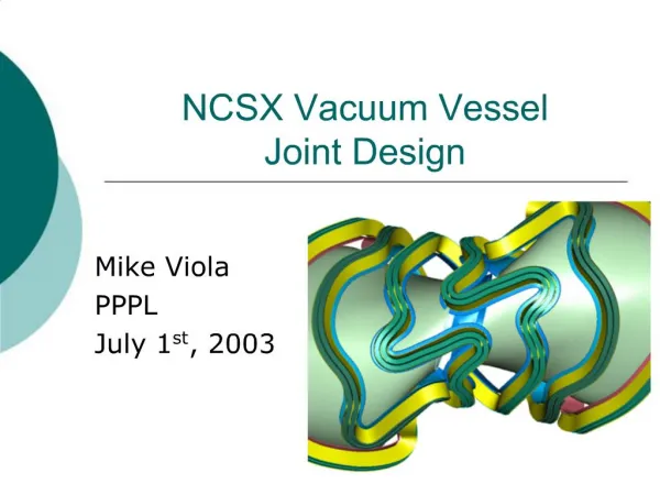
Vessel Concepts – DesignStudy Ship-shaped, floating self-propelled, DP-stabilised vessel specialised for foundation installation(FTIV) Ship-shaped, self-propelled and self-elevatedvessel specialised for foundation installation(FTIJ) Ship-shaped, self-propelled and self-elevated vessel specialised for turbine installation(WTIJ)
Concept SelectionProcess Design implications Importan cefactor Location Sub-criteria VESSELCONCEPT Operational phases& tasks Ranking Types Reduce Carry Wide Optimised Average Δ T imeincurred or saved per turbine Cost incurredor saved per turbine Factor Factored Factored cost& time bigger turbines weather window for site & transitop.’s #1FTIV 2 2 2 1 1.75 SPIV (Jack up vessel) specialised for turbine installation -0.2 -0.6 0.3 0.9 1. #2FTIJ 2 1 3 2 2 Case 0 –South Knock Deck seafastening system for components/equipm ent Mobilisation 3 #3WTIJ 3 3 3 3 3 Crane liftfor components Load-out 5 -0.8 -4 -0.5 -2.5 OperationalCriteria 1- Lesslikely 2-Likely 3-Highlylikely Component positioningand fixing 4 -0.8 -3.2 -0.5 -2 Ballastingfor jacking / submerging procedure 2 -0.2 -0.4 -0.1 -0.2 Ballasting fortrim 2 0 0 -0.1 -0.2 Number/size of turbinecomponents 4 -0.9 -3.6 -0.5 -2 Transit tosite Transitspeed 3 -0.2 -0.6 -0.2 -0.6 TransitHs 4 -0.5 -2 -0.2 -0.8 Transit windspeed 3 -0.1 -0.3 -0.5 -1.5 Ship-shaped, self propelled and self- elevated vessel specialised forturbine installation (WTIJ) Route 3 -0.2 -0.6 0 0 Positioning onsite DPoperations 3 0 0 0 0 Jacking, hull elevation,pre- loading 3 -0.2 -0.6 -0.4 -1.2 Jack-down 3 -0.1 -0.3 -0.4 -1.2 Foundation handling Lifting andHandling 5 0.7 3.5 0.4 2 Foundation Installation Positioning / Upendingand Hammering 4 0.7 2.8 0.7 2.8 TPInstallation Lifting andgrouting 3 0.5 1.5 0.4 1.2 TurbineInstallation Seafastenings 3 -0.2 -0.6 0.3 0.9 Techniciantransfer toTP 5 -0.8 -4 -0.2 -1 Lifting components andassembly 5 -1 -5 -0.8 -4 Helicopter operations forcrew change Crewchange 1 -0.1 -0.1 0.1 0.1
WTIJ DesignSelection • Key parameters • Cargo Selection &Capacity • Vessel Economics • CAPEX &OPEX • Timereduction • Port and Siterestrictions • Craneoperations
Vessel Economics – TurbineSelection Time to install(days) Hundreds 2.0 150NM 100NM 50NM 20NM Effective Installation cost perturbine Thousands 1.8 €480.00 5, €474.48 €470.00 Sample Vessels Installation cost perturbine €460.00 1.6 5 6 7 8 9 1011 No of turbines pervessel €450.00 €440.00 Installationtime 6, €435.56 €430.00 11, €428.71 €48 €46 €44 €42 €40 €38 €36 €34 €420.00 InstallationCost Millions 9, €414.55 7, €410.38 €410.00 150NM 100NM 50NM 20NM 8, €406.10 €400.00 8, €392.09 8 TurbineNumber €390.00 4 6 10 12 5 6 7 8 9 10 11 No of turbines pervessel Installationcost Courtesy: Geosea Maintenance (DEMEGroup)
Installation Vessel DesignFeatures • Ship type selfelevating vessel(168.5x50x12) • Pedestal Crane (Max.1500t) • Dual FuelEngine • Cargo Capacity (9000t)
Examples of Concept Design Activities Hull Form Design, Optimisation & CFDAnalysis LegLength Calculation DPCalculation Conical spudcan for easy assembly StabilityCalculations Electric LoadCalculations StructuralCalculations
Key Elements of WTIJConcept • Pure LNG propulsionsystem • Capable to operate in all regions ofECA • Capable to carry and mount 8 units of 8MW (or 7 pieces of 10MW) wind turbines (for 10MW subject to designfeatures) • Capable to install 32 wind turbines with 4 visits without refuelling • Capable to install wind turbines with 1500-ton main crane or to install both wind turbines and monopile foundations (4 pcs) with 2000-ton maincrane • Capable to operate under higher wind speed conditionsvia • high wind boom lock system for installation of suspendedweights • Environmental Regularity Number = (99, 99, 98, 98, 84) for dynamic positioning operations with existing propulsion and thrustersystem • 6040 m2 free main deck area optimized for fastinstallation • 70 person capacity (crew +technicians)
Simulation Activities -Scope • Simulator based studies supporting: • FeasibilityStudies for innovativedesign • solutions • Development of OperationalProcedures • Training of crews andoperators • Development of thrust allocation strategies • Development and tuning of DPsystem • Development of combined/integrated operational procedures for DP and crane operations • Determination of weather windowsfor • safe operation
Leanwind Project SimulatorDemo • K-Sim simulatormodel consistingof • Vessel hydrodynamical model based on design principles • Corresponding K-Pos DP SW with current off theshelf wind turbine installation and servicefunctionality • Installationcrane • 4-leg jackingsystem • Deck layout for 8 x 8MW turbines • Operator environment forDP, jacking operator and crane operator
Commercial Benefits forLR Update ofLR rules and guidance Testingimpacts of regulatory changes Opportunitiesto Class New Build/TOC Access to information regarding corporateplans for new innovation and costreduction LR Installationvessel concept design support Strategic Offshore Wind market entry/design optimisationfor vesselowners Wind Turbine Foundation Certification (Design andMnf Review) O&Mvessel operations supportIRIS Scourmodelling on windfarms
Rules and guidance – Classification of Wind Farm ServiceVessels Guidance Notes for the Classification of WindFarm ServiceVessels The growing market for offshore wind farmshascreatedanindustryrequirement for service vessels to support the construction and installation of the associated wind turbines. Typically these vesselsareengagedinferrying workersandlightcargoestothewind turbines for construction and routine maintenance. This guidance note is designed to assist designers,builders,operatorsandowners wishing to Class their Wind Farm Service Vessels with Lloyd’sRegister (hereinafter referred to as LR). For the Classificationofthesevessels,allpartsthe LR Rules and Regulations for the Classification of Special Service Craft (hereinafterreferredtoastheRules forSpecialServiceCraft)aretobeapplied
Rules andGuidance • GuidanceNotesforWindTurbineInstallationVessels • ThisGuidanceNoteprovidessummaryinformationfordesignersandoperatorsconcerningclassificatio requirements for offshore units engaged in installation and / or maintenance activities relating to offshore windturbines. • ItisintendedthatforthesetypesofunitsclassnotationsareassignedinaccordancewithPart1of ourRulesandRegulationsfortheClassificationofOffshoreUnits. • Thefollowingtypesofvessels(WTIVs)arecoveredbythisGuidanceNote: • Surface-type floatingunit; • Surface-type self-elevatingunit; • Self-elevatingunit; • Column-stabilisedunit.
The research leading to these results has received funding from the European Union Seventh Framework Programme under the agreementSCP2-GA-2013-614020.
MarkAnju Venkata Swarupanand Godavarthi(Anand) Lloyd’s RegisterEMEA Global Technology Centre, BoldrewoodCampus Burgess Road, Southampton SO167QF T +44 (0)330 4140455/1056 E swarupanand.godavarthi@lr.org/mark.anju@lr.org w www.lr.org Workingtogether for a saferworld