Download
1 / 43
430 likes | 530 Views
Opposed-Flow Flame Spread in Different Environments. Subrata (Sooby) Bhattacharjee San Diego State University. Acknowledgement. Profs. Kazunori Wakai and Shuhei Takahashi, Gifu University, Japan Dr. Sandra Olson, NASA Glenn Research Center.

E N D
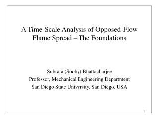
Opposed-Flow Flame Spread in Different Environments Subrata (Sooby) Bhattacharjee San Diego State University
Acknowledgement • Profs. Kazunori Wakai and Shuhei Takahashi, Gifu University, Japan • Dr. Sandra Olson, NASA Glenn Research Center. • Team Members (graduate): Chris Paolini, Tuan Nguyen, Won Chul Jung, Cristian Cortes, Richard Ayala, Chuck Parme • Team Members (undergraduate): Derrick, Cody, Isaac, Tahir and Mark. (Support from NASA and Japan Government is gratefully acknowledged)
Overview • What is opposed-flow flame spread? • Flame spread in different environment. • Recent experiments at MGLAB, Japan • Mechanism of flame spread. • Length scales and time scales. • Spread rate in normal gravity. • Spread rate in microgravity • The quiescent limit • Future plan.
Upward or any other flow-assisted flame spread becomes large and turbulent very quickly. Opposed-flow flame spread is also known as laminar flame spread.
Downward Spread Experiment, SDSU Combustion Laboratory PMMA: = 10 mm = 0.06 mm/s AFP: = 0.08 mm = 1.8 mm/s
Sounding Rocket Experiment Spread Over PMMA: Infrared Image at 2.7m mm • Gravity Level: 1.e-6g • Environment: 50-50 O2/N2 mixture at 1.0 atm. • Flow Velocity: 50 mm/s • Fuel: Thick PMMA (Black) • Spread Rate: 0.45 mm/s
Experiments Aboard Shuttle: O2: 50% (Vol.), P=1 atm. Image sequence showing extinction Fuel: Thin AFP, =0.08 mm = 4.4 mm/s Vigorous steady propagation. Thick PMMA
N2 port Igniter (Ni-Cr wire) O2 port Vacuum pump port Vf Manometer port Vf Vg Vg~300mm/sec Fuel holder Fuel holder PMMA : 30mm x 10mm x 15,50,125mm Side view camera Front view camera CCD camera CCD camera Honeycomb Fuel holder Igniter (Ni-Cr wire) Fan Air O2 Vacuum Air Fuel holder PMMA: 30mm x 10mm x 15,50,125mm Igniter (Ni-Cr wire) Apparatus for normal-gravity experiments Apparatus for micro-gravity experiments conducted with the 4.5sec trop-tower (100meter-drop) of MGLAB in Japan.
Front view Solenoid coil to remove the igniter at the onset of MG Video camera Sample holder (sample size: 6cm x 1cm) Fan & Motor Motor controller Back view
Assemble Move to drop shaft Close the capsule Ready to drop Attach the transceiver
MG for 4.5 sec The onset of MG Ignite the sample 1.6 sec before MG. Declaration G in the friction damper. Remove the igniter 0.3sec before MG. Typical sequence of the drop experiment
O2: 30%, 1 atm. PMMA: = 0.025mm = 10 mm/s (Downward spread) = 4.1 mm/s (MGLAB drop tower)
O2: 50%, 1 atm. PMMA: = 0.025mm = 22.8 mm/s (Downward spread) = 18.9 mm/s (MGLAB drop tower)
Mechanism of Flame Spread Flame seeks out the stoichiometric locations O2/N2 mixture Fuel vapor Virgin Fuel The flame spreads forward by preheating the virgin fuel ahead.
Mechanism of Flame Spread O2/N2 mixture Vaporization Temperature, Virgin Fuel The rate of spread depends on how fast the flame can heat up the solid fuel from ambient temperature to vaporization temperature .
Forward Heat Transfer Pathways: Domination of Gas-to-solid Conduction (GSC) The Leading Edge Gas-to-Solid Conduction Pyrolysis Layer Preheat Layer Solid-Forward Conduction
Zooming on the Leading Edge Gas-phase conduction being the driving force,
The Characteristic Heating Rate Sensible heating (sh) rate required to heat up the unburned fuel from to Flame Temperature, Vaporization Temperature, Heating rate due to gas-to-solid (gsc) conduction: Ambient Temperature,
Spread Rate Expressions Flame Temperature, Conduction-limited or thermal spread rate: Vaporization Temperature, For semi-infinite solid,
Spread Rate Expressions Flame Temperature, Conduction-limited spread rate: Vaporization Temperature, For thermally thin solid,
Hang-Distance Correction for Thin Fuels [Bhattacharjee, Combustion and Flame, 94] The Extended Simplified Theory (EST) retains the same form as the de Ris expression and recommends for evaluating properties. Hang-distance, the distance between the flame front and the pyrolysis front, is ignored in de Ris solution. Flame front. Pyrolysis front
Extended Simplified Theory – Thick Fuels[Bhattacharjee et al., 26th Symp] Introduce a correction for the lifted flame through The Extended Simplified Theory (EST) retains the same form as the de Ris expression and recommends for evaluating properties. Replace the forced or buoyancy induced boundary layer with an equivalent slug flow. Thick Fuel Spread Rate (EST):
There are Hardly Any Studies on Transition in Literature Most thin fuel studies were done with cellulose Most thick fuel studies were done with PMMA
It Maybe Easier to Study Transition in the Absence of Buoyancy Thin-fuel formula Thick-fuel formula At low opposing velocity, critical thickness can be a hundred time larger, removing the difficulty of creating thin samples. The intersection produces:
Thoery, Numerical Simulation and Existing Data where, Spread Rate [cm/s]
where and for thermally-thin fuel for thermally-thick fuel Downward spread rate vs. fuel half-thickness in normal-gravity
where Non-dimensional downward spread rate vs. non-dimensional fuel half-thickness
Parallel Heat Transfer Mechanisms Gas to Environment Radiation (ger) Gas to Solid Radiation (gsr) Solid to Environment Radiation (ser) Gas to Solid Conduction (gsc) Solid Forward Conduction (sfc)
Time Scales The characteristic heat is the heat required to raise the solid-phase control volume from to . Gas to Solid Conduction (gsc) Gas-to-surface conduction time:
Relative dominance of GSC over SFC Gas to Solid Conduction (gsc) Solid Forward Conduction (sfc)
Radiative Term Becomes Important in Microgravity Solid to Environment Radiation (ser) The radiation number is inversely proportional to the velocity scale. In the absence of buoyancy, radiation can become important. Gas to Solid Conduction (gsc) Solid Residence Time:
Mild Opposing Flow: Computational Results for Thin AFP As the opposing flow velocity decreases, the radiative effects reduces the spread rate
Spread Rate in the Microgravity Regime Solid to Environment Radiation (ser) Include the radiative losses in the energy balance equation: Gas to Solid Conduction (gsc) Algebraic manipulation leads to:
The Quiescent Microgravity Limit: Fuel Thickness Solid to Environment Radiation (ser) The minimum thickness of the heated layer can be estimated as: Gas to Solid Conduction (gsc) All fuels, regardless of physical thickness, must be thermally thin in the quiescent limit.
The Quiescent Microgravity Limit: Spread Rate Solid to Environment Radiation (ser) The spread rate can be obtained from the energy balance that includes radiation. Gas to Solid Conduction (gsc) reduces to: where,
The Quiescent Limit: Extinction Criterion In a quiescent environment steady spread rate cannot occur for
The Quiescent Limit: MGLAB Experiments Extinction criterion proposed is supported by the limited amount of data we have acquired thus far.
Igniter for concurrent-flow spread. The fuel is spooled from B to A Average velocity Centerline velocity Igniter for opposed-flow spread. The fuel is spooled from A to B Oxygen/Nitrogen Mixture Smoke Wire Spot Radiometer Flow Modifier reduces the entrance length. C D A B E Imaging window backlit with IR radiation Control Thermocouple: The conveyor belt holding the fuel is spooled from roller A to B so as to maintain a constant thermocouple temperature. Side View Top View A B IR Source with beam expander C IR Camera with a rotating filter wheel containing 4.3 mm and 2.8 mm filters of varying trasmittance. Thin PMMA sheet (thickness 200 mm or less) attached on a conveyor belt.
Future Work • The MGLAB data suffers from limited low-g duration (4.5 s) to distinguish steady spread from a spreading extinction. Only space experiment can establish the microgravity and quiescent formulas proposed. • While this work predicts extinction for fuel with thickness greater than a certain critical thickness, the pathway to extinction is not clear. Detailed infrared emission and absorption photography will be used to establish the role played by radiation. • Numerical modeling and a comprehensive set of data with flow velocity, oxygen level, ambient pressure and fuel thickness as parameters from an ambitious flight experiment will be used to quantify the transition between thin and thick fuels, thermal, microgravity and quiescent regimes, and wind opposed and wind aided spread. • A novel experimental set up is being built at SDSU, where the fuel is moved relative to the flame so as to keep the flame stationary with respect to the laboratory. The absorption pyrometry is being developed at Gifu.