Download
1 / 38
400 likes | 651 Views
Qualified Partner Program Fiber Optic Cables basics - GOF, HCS and POF. Felice Guarna, Training Program Manager Wetzikon, January 2006. Agenda. Cable structure Primary coating and buffers Armouring Outer jacket GOF cables HCS cables PMMA cables. Cable structure.

E N D
Qualified Partner ProgramFiber Optic Cables basics - GOF, HCS and POF Felice Guarna, Training Program Manager Wetzikon, January 2006
Agenda • Cable structure • Primary coating and buffers • Armouring • Outer jacket • GOF cables • HCS cables • PMMA cables
Cable structure • Fiber is mechanically weak • Cable adds protection and prevents physical damage during installation and use. • Combination and quantity of protections and material as well as construction are strictly dependent on cable environment • Indoor • - Ducts- Trays- Building raiser- Plastic pipes- Raised floors- Plenum (US) • Outdoor • - Empty pipes- Ducts- Trays- Direct burial- Aerial
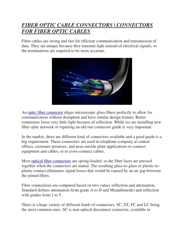
Fiber Optic Cable F.O. cable construction generalities Fiber Secondary Coating (Buffer) Outer jacket Armouring
The optical fibers we are considering PMMA Polimetilmetalcrilate HCSF Hard Clad Silica Fiber GOF Glass Optical Fiber
Seconday coating (buffer types) Tight Buffer A thermoplastic material is extruded tight on one fiber or around several fibers. They are called ribbons. Optical Fiber Tight Sheath Semi-Tight Buffer Loosely buffered with a few µm of interspaces. Gel-like Compound or dry Optical Fiber Loose Sheath
Buffer types Single Loose Tube Tube with one fiber. Loose sheath with some hundreds of millimeters of inner space. Gel-like Compound or dry Optical Fiber Loose Sheath Loose tube (2 – 4 mm)Loose sheath/tube with 2 - 24 optical fibers.The hollow space is filled with a gel. Gel-like Filling Compound Optical Fiber Loose Sheath
Armoring • Depending on the environment (in or outdoor) the armouring can vary: • Aramid yarn for pulling and crushing strength • Glass yarn for pulling strength and crush rodent protection • Water blocking tape/gel resists longitudinal water intrusion • Corrugated steel tape rodent protection chemical resistant
Outer jacket protections The armoring and sheath material are designed to protect the fiber from the following effects The material also influences easy handling and flexibility for specific application such as bending, torsion, flexing, kink, repeated bending
Outer jacket material properties • Please note: depending on the recipe of the material the properties may change.
Outer jacket material fire and environmental properties (FRNC, LSOH, LSZH) • In case of a fire the material should not spread fire and should not emit toxic and corrosive gas to protect first people and then equipment.
GOF cables Glass optical fiber
Fiber primary coating and color coding Primary Coating250m Cladding125m Fiber Corexm (x = 9, 50, 62.5) • Color codes for fiber and buffer • Each fiber in a cable is individually marked. • Country or manufacturer specific color coding order
Position Code Notes Position Code Notes 1 2 3 4 5 6 I- V W D (ZN) Y H n bzw. nxm E G Indoor cable buffered fiber (tight or semi-tight buffered ) air tube loose tube non-metallic strength member PVC-jacket jacket of halogen-free, flame-retardant material Number of fiber or number of loose tubes x no. of fiber per tube single-mode fiber (glass/glass) multi-mode fiber (glass/glass) 7 8 9 10 11 12 n/ n n B F F H n LG Field Ø (µm) at SM Core Ø (µm) at MM cladding diameter (µm) attenuation (dB/km) 850 nm at MM 1300 nm at MM 1310 nm at SM 1550 nm at SM Dispersion (ps/nm x km) at single-mode fiber; Bandwidth (MHz/km) at multi-mode fiber Layer-stranding DIN coding for fiber optic indoor Cables
DIN coding for fiber optic outdoor cables Position Code Notes Position Code Notes Outdoor cable metallic strength member in the center air tube Loose tube metallic twisting element filling compound in the void PE-jacket Composite layer sheath of Al-tape and PE PE-jacket with nonmetallic strain relief elements Aluminum tape and PE with nonmetallic strain relief elements Amour Amour with PVC-jacket Amour with PE-jacket 1 2 3 4 5 6 7 A- (ZS) W D S F 2Y (L)2Y (ZN)2Y (L)(ZN)2Y B BY B2Y 8 9 10 11 12 13 14 15 n or nxm E G n n n B F F H n LG BD u Number of fiber or number of loose tubes x no. of fiber per tube (e.g. 6x4... ) Single-mode fiber pure silica Multi-mode fiber pure silica Field diameter (µm) at SM Core diameter (µm) at MM cladding diameter (µm) attenuation (dB/km) wavelength 850 nm at MM 1300 nm at MM 1310 nm at SM 1550 nm at SM Dispersion (ps/nm x km) at single-mode fiber; Bandwidth (MHz/km) at multi-mode fibers Layer-stranding Unit stranding Non stranding
Mini-Breakout cable • Distribution cable • Easy direct connector mounting • Small dimension • flexible Outer sheath Armoring/strength members Tight or semi-tight buffer (up to 900µm) Fiber
Full-breakout cable • Patch Cord • Distribution cable • Direct connector mounting • Strain relieve for individual fiber Zipcord Figure-0 Outer sheath Armoring/strength members Tight or semi-tight buffer (up to 900µm) Fiber
Loose tube cable Tube with up to 24 fibers (250µm) Strength members Outer sheath Corrugated steel tape Tube with up to 24 fibers (250µm) Strength members Outer sheath
Stranded loose tube cable Tube with up to 24 fibers (250µm) Several layers of tubs for 432 fibers Central strength member Strength members Outer sheath
Aerial cables (figure 8 design) • Installation load should be calculated.Wind, ice and snow load as well as possible electrical fields should be considered during planning. Steel suspension wire Tubes with fibers (250µm) Central strength member Outer sheath
Aerial cables (all dielectric, self supporting - ADSS-design) • Installation load should be calculated.Wind, ice and snow load as well as possible electrical fields should be considered during planning. Tubes with fibers (250µm) Central strength member Strength member Outer sheath
Metallic cables • Aerial cable • Aerial ground wire Stainless steel loose tube Fibers Aldrey, steel or ACS wires • Installation load should be calculated.Wind, ice and snow load as well as possible electrical fields should be considered during planning.
PCF cables Polymer clad fiber
POF (Plastic Optical Fiber) terminology PMMA PCF traditional perfluorinated Core Acrylic Acrylic Glass Cladding Fluorinated Polyperfluoro Fluorinated butenylvinylether PROCESS Plasma OVD draw extrusion extrusion
Cables • Basically similar or same construction as GOF • Larger core • Simplex and Duplex figure 8 or round cable • Loose tube • Applications • Medical Industrial/Scientific Laser surgery Angioplasty Lithotripsy Urology Dermatology Photodynamic therapy Spectroscopy Remote illumination Sensors Thomson scattering
PMMA plastic optical fiber Plastic optical fiber
Index profiles • PMMA Step Index • core = Constant refractive index • PMMA Graded Index • Core = several layer of material with different refractive indexes • Perfluorinated Polymer Graded index • Core = parabolic index
Step Index polymer optical fiber (SI-POF) • Core Ø 980 μm • Cladding Ø 1000 μm • Attenuation 180 dB/km • Bandwidth 10 MHz .100m (100 MHz .100m) • Wavelength 650nm • N.A. 0.5 (Low N.A. 0.3) • Ader tight buffer • Advantage easy, fast and inexpensive connection technologycommercially available (Mitsubishi, Toray, Fuji, Optimedia) • Disadvantage high attenuation, low bandwidth
Multistep Index Plastic Optical Fiber (GI-POF) • Core Ø 900 μm • Cladding Ø 1000 μm • Attenuation 180 dB/km • Bandwidth 100 MHz .km • Wavelength 650nm • Cable tight buffer • Advantage easy, fast and inexpensive connection technologycommercially available (Mitsubishi, Fuji, Optimedia) • Disadvantage high attenuation
Graded Index Plastic Optical Fiber (GI-POF) • Core Ø 120 μm • Cladding Ø 500 μm • Attenuation 50 dB/km • Bandwidth 1000 MHz*km • Wavelength 1330nm • Cable loose buffer (extra strength members) • Advantage low attenuation, high bandwidth • Disadvantage termination, expensive, similar to GOFcommercially not available (Asahi, Nexans, Chromis)
Plastic optical fiber IEC 60793-2-4 – Specification for category A4 multimode fiber
Simplex and Duplex cables (PMMA fiber) Tight buffer Core Cladding • Tight Buffer • Tightly buffered with a thermoplastic material. • PMMA POF - Step Index, Multistep, Graded Index Tight buffer Core Cladding
Duplex cables (perfluorinated fiber) • Single loose tube • Loose sheath with air cap (µm up to mm). Dry – no gel • Perfluorinated POF • Graded Index Outer sheath lose buffer Core Cladding Strength member
Cable for harsh environment (PMMA fibers) Outer sheath • Tight Buffer • Tightly buffered with a thermoplastic material. • PMMA POF - Step Index, Multistep, Graded Index • Outer sheath and strength memberse.g. PUR outer sheath and aramid yarns for drag chain and harsh industrial environments Filling element Tight buffer Core Cladding Strengthmember