Download
1 / 73

E N D
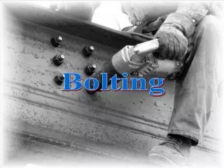
Bolting and Welding
Introduction This presentation was developed as a teaching aid with the support of the American Institute of Steel Construction. Its objective is to provide technical background and information for bolting and welding. The information provided is based on common design and construction practices for structures of twelve stories or less. The AISC Digital Library case study presentations document the construction of a steel frame for an office building. The case study includes photographs that were taken throughout the construction of the structural steel frame including detailing, fabrication, and erection. Project data including plans, schedules, specifications and other details are also included. The case study presentations are available in the Learning Opportunities section at www.aisc.org. This presentation provides technical information on bolting and welding, as well as the impacts of details and design choices on schedule, cost, sequence and overall project management. The information is presented with concerns of a construction manager or general contractor in mind.
What Will You Gain From This Presentation? • General knowledge of structural steel • An understanding of the different ways that structural steel is connected • Insight into types of bolts and their installation • An awareness of types of bolted joints used for structural steel • Knowledge of welding terminology, weld types, and welding processes • Familiarity with common weld inspection methods and considerations associated with field welding
Benefits of Structural Steel • Some benefits associated with use of structural steel for owners are: • Steel allows for reduced frame construction time and the ability to construct in all seasons • Steel makes large spans and bay sizes possible, providing more flexibility for owners • Steel is easier to modify and reinforce if architectural changes are made to a facility over its life • Steel is lightweight and can reduce foundation costs • Steel is durable, long-lasting and recyclable (AISC 1999)
Unique Aspects of Steel Construction Procurement and management of structural steel is similar to other materials, but there are some unique aspects to steel construction: • Steel is fabricated off-site (above left) • On-site erection is a rapid process (above right) • This gives use of structural steel some scheduling advantages • Coordination of all parties is essential for achieving potential advantages • (AISC 1999)
Connecting Structural Steel • The primary connection methods for structural steel are bolting and welding • A structure’s strength depends on proper use of these connection methods • Connections made in a fabrication shop are called shop connections • Connections made in the field by the steel erector are called field connections • Bolting and welding may be used for shop connections and field connections
Connecting Structural Steel • A fabrication shop will have a desired fastening method suited to its equipment and fabrication methods • Field connections are typically bolted • Welding may be used for field connections where bolting is either impractical or undesirable • Welding is better suited to the controlled environment of a fabrication shop
Structural Bolting • The Research Council on Structural Connections (RCSC) prepares specifications and documents related to structural connections • RCSC’s Specification for Structural Joints Using ASTM A325 or A490 Bolts (2000) is a widely used specification which discusses joints, fasteners, limit states, installation, and inspections
Structural Bolting • During hoisting, connectors will install a minimum of two bolts per connection • The rest of the bolts are installed and tightened after the structure is plumbed • A systematic pattern must be followed when tightening bolts so that a joint is drawn together and all fasteners are properly installed • (SSTC 2001)
Structural Bolting Per the Occupational Safety & Health Administration Standard 1926.754(b)(2), “At no time shall there be more than four floors or 48 feet (14.6 m), whichever is less, of unfinished bolting or welding above the foundation or uppermost permanently secured floor, except where the structural integrity is maintained as a result of the design.”
Structural Bolting (AISC & NISD 2000) • There are many bolt types, installation methods, and joint types used in structural steel construction • When left exposed, bolts may be used to make an architectural expression • (Green, Sputo, and Veltri)
ASTM Bolt Types (AISC & NISD 2000) • A307 – Low carbon steel • Not commonly used • Only used for secondary members • A325 – High-strength medium carbon steel (above left) • Most common bolts used in building construction • A490 – High-strength heat treated steel (above right) • Cost more than A325’s, but are stronger so fewer bolts may be necessary • Note that the ASTM designation is indicated on the head of the bolts above
Common Bolt Sizes • A325 and A490 bolts are available in diameters ranging from 1/2” to 1-1/2” • The most common sizes are 3/4”, 7/8”, and 1” • High-strength bolts are commonly available in incremental lengths up to 8” • (AISC)
Washers • Hardened steel washers are used in many structural connections to spread pressure from the bolt tightening process over a larger area • Washers may also be used to cover an oversized or slotted hole (RCSC 2000) • Flat washers are most commonly used • Tapered washers (above left) are used when the surface being bolted has a sloped surface, such as the flange of a channel or an S shape • A325 bolts require a washer under the element (head or nut)being turned to tighten the bolt (shown under the nut, above right) • A490 bolts require a washer under both the head and nut (AISC & NISD 2000)
Parts of the Bolt Assembly Grip Washer Nut Washer Face Shank Thread Head Length • Grip is the distance from behind the bolt head to the back of the nut or washer • It is the sum of the thicknesses of all the parts being joined exclusive of washers • Thread length is the threaded portion of the bolt • Bolt length is the distance from behind the bolt head to the end of the bolt • (AISC & NISD 2000)
Bolted Joint Types • There two basic bolted joint types: • Bearing • The load is transferred between members by bearing on the bolts • Slip-critical • The load is transferred between members by friction in the joint
Bolted Joint Failure Modes Bearing Fracture Bearing Fracture Bearing Yield Bearing Yield • Bolts in bearing joints are designed to meet two limit states: • Yielding, which is an inelastic deformation (above left) • Fracture, which is a failure of the joint (above left) • The material the bolt bears against is also subject to yielding or fracture if it is undersized for the load (above right) • Tension connections act similarly to bearing connections • Many times, connections in direct tension are reconfigured so that the bolts act in shear (AISC)
Bearing Joints • In a bearing joint the connected elements are assumed to slip into bearing against the body of the bolt • If the joint is designed as a bearing joint the load is transferred through bearing whether the bolt is installed snug-tight or pretensioned (AISC)
Threads in the Shear Plane • The shear plane is the plane between two or more pieces under load where the pieces tend to move parallel from each other, but in opposite directions • The threads of a bolt may either be included in the shear plane or excluded from the shear plane • The capacity of a bolt is greater with the threads excluded from the shear plane • The most commonly used bolt is an ASTM A325 3/4” bolt with the threads included in the shear plane • (AISC & NISD 2000) Threads Included In The Shear Plane Threads Excluded From The Shear Plane
Slip-Critical Joints • In a slip-critical joint the bolts must be fully pretensioned to cause a clamping force between the connected elements • This force develops frictional resistance between the connected elements • The frictional resistance allows the joint to withstand loading without slipping into bearing against the body of the bolt, although the bolts must still be designed for bearing • The faying surfaces in slip-critical joints require special preparation (AISC)
When to Use Slip-Critical Joints Per the RCSC Specification (2000), Slip-critical joints are only required in the following applications involving shear or combined shear and tension: • Joints that are subject to fatigue load with reversal of the loading direction (not applicable to wind bracing) • Joints that utilize oversized holes • Joints that utilize slotted holes, except those with applied load approximately perpendicular to the direction of the long dimension of the slot • Joints in which slip at the faying surfaces would be detrimental to the performance of the structure
Snug-tight Installation Snug-tight is the tightness attained with a few hits of an impact wrench or the full effort of an ironworker using an ordinary spud wrench to bring the connected plies into firm contact (RCSC 2000)
Turn-of-Nut Installation • Installation beyond snug-tight is called pretensioning • Turn-of-nut pretensioning involves several steps: • The bolt is snug-tightened • Matchmarks are placed on each nut, bolt, and steel surface in a straight line • The part not turned by the wrench is prevented from turning • The bolt is tightened with a prescribed rotation past the snug-tight condition • The specified rotation varies by diameter and length (between 1/3 and 1 turn) • (RCSC 2000, AISC)
Calibrated Wrench Installation • Calibrated Wrench pretensioning uses an impact wrench (above left) to tighten the bolt to a specified tension • A Skidmore-Wilhelm calibration device (above right) is used to calibrate the impact wrench to the torque level which will achieve the specified tension • A sample of bolts representative of those to be used in the connections are tested to verify that the correct tension will be achieved (RCSC 2000, AISC)
ASTM F1852 Installation (AISC) • F1852 bolts are twist-off-type tension-control bolts • These bolts must be pretensioned with a twist-off-type tension-control bolt installation wrench that has two coaxial chucks • The inner chuck engages the splined end of the bolt • The outer chuck engages the nut • The two chucks turn opposite to one another to tighten the bolt • The splined end of the F1852 bolt shears off at a specified tension (AISC 2003)
ASTM F959 Direct Tension Indicators DTI’s Feeler Gages • Another way to try to ensure proper pretensioning of a bolt is through the use of direct tension indicators (DTIs) • These washers have protrusions that must bear against the unturned element • As the bolt is tightened the clamping force flattens the protrusions and reduces the gap • The gap is measured with a feeler gage • When the gap reaches the specified size the bolt is properly pretensioned • (AISC & NISD 2000)
Installation of DTIs (Adapted from Figure C-8.1 RCSC 2000) • It is essential that direct tension indicators be properly oriented in the assembly • The bolt head is stationary while the nut is turned – DTI under bolt head • The bolt head is stationary while the nut is turned – DTI under nut (washer required) • The nut is stationary while the bolt head is turned – DTI under bolt head (washer required) • The nut is stationary while the bolt head is turned – DTI under nut • (RCSC 2000)
Nominal Bolt Hole Dimensions (Table 3.1 RCSC 2000) • Bolts are installed in one of four types of holes (see table above) • Standard holes can be used anywhere • Oversized holes may only be used in slip-critical connections • Short-slotted holes are used with the slot perpendicular to the direction of stress • Long-slotted holes are primarily used when connecting to existing structures
Equipment Requirements • Common tools used by Ironworkers include spud wrenches, pins, and corrections bars of various sizes (above left) • Impact wrenches will be needed for certain installations (above center) • Electricity or compressed air is required depending on the impact wrench being used • A generator as well as an air compressor may be needed (above right)
Storage of Components • Per the RCSC Specification: • Fastener components must be protected from dirt and moisture in closed containers on the jobsite • Only fasteners anticipated to be installed during the work shift are to be taken from protected storage • Protected storage is defined as the continuous protection of fastener components in closed containers in a protected shelter • Any unused fasteners must be promptly returned to protected storage
Storage of Components • The lubrication on fasteners is vital to their proper installation • A water-soluble oil is used on most black bolts • This oil is easily washed off when exposed to moisture • Fasteners that accumulate rust or dirt must be cleaned and relubricated before they may be installed • F1852 bolts (shown above) shall not be relubricated, except by the manufacturer (RCSC 2000, SSTC 2001)
Storage of Galvanized Fasteners • Galvanized bolts and nuts (above) are provided by the supplier in a set and special storage requirements • Each bolt/nut set is pretested by the supplier and shipped together and must be kept together as an assembly • Poor thread fit may result if the bolt and nut are mismatched • The lubrication on galvanized fasteners is generally more durable than that on black bolts, but protected storage is still recommended • A490 bolts are not allowed to be galvanized (SSTC 2001)
Production Lots • Production lot traceability is required by many standards • Even if not required, it is good practice to record the lot numbers and keep all fasteners separated by lot • It is necessary to keep lots separate for proper pre-installation verification testing which is required for pretensioned and slip-critical joints • Mixing bolts and nuts from different production lots is not permitted • (SSTC 2001)
Inspections • In addition to the erector’s quality control program, tests and inspection are specified by the Engineer of Record and/or the local building authority • A local building inspector may request that tests in addition to those specified by the Engineer of Record be performed • Snug-tightened joints require visual inspection for firm contact and proper use of washers • Pretensioned joints require pre-installation verification and routine observation of proper application • Slip-critical joints require inspection of the faying surfaces in addition to the above inspections
Inspections for the Construction Manager There are several bolted connection inspections a construction manager can perform: • Look at the bolt stick-out (above) • Stick-out is the amount the bolt extends beyond the outside surface of the nut • Positive or zero stick-out is acceptable • Negative stick-out, where the end of the bolt is inside the nut, is not acceptable
Inspections for the Construction Manager • Inspect the turn-of-nut matchmarks to ensure the bolts have been pretensioned • If F1852 bolts are used, make sure the ends have been snapped off all bolts (above) • In some cases, due to insufficient clearance for the installation wrench, F1852 bolts will be tightened by alternative methods so the ends will not be snapped off
Bolting Cost Considerations The types of joints used in a structure are somewhat dependent on the overall design of the structure, but these are some points to consider: • The erector may prefer certain bolt and joint types over others due to equipment requirements, experience, and installation times • Snug-tightened joints are normally the most economical bolted joints (Ruby 2003) • For pretensioned joints, F1852’s and DTI’s are popular and can be economical • Slip-critical joints are the most costly joints, and should only be specified when necessary (Ruby 2003)
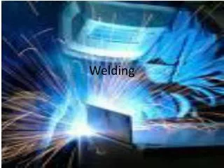
Structural Welding • Another common method for connecting structural steel is welding • Welding can be performed in the shop or in the field • Many fabrication shops prefer to weld rather than bolt • Welding in the field is avoided if possible due to welding condition requirements • There are several welding processes, types, and positions to be considered in building construction
Structural Welding • The American Welding Society (AWS) is a nonprofit organization with a goal to advance the science, technology and application of welding and related joining disciplines • AWS develops codes, recommended practices, and guides under strict American National Standards Institute (ANSI) procedures • D1.1 Structural Welding Code – Steel, one of the most consulted codes in the world, is produced by AWS (AWS 2004a)
Structural Welding • Welding is the process of fusing multiple pieces of metal together by heating the filler metal to a liquid state • A properly welded joint is stronger than the base metal
Strength of Structural Welds (Part of Table J2.5 AISC 2005) • Welds may be loaded in shear, tension, compression, or a combination of these • Capacities for welds are given in the AISC Specification Section J2 (2005) • The strength of a weld is dependent on multiple factors, including: base metal, filler metal, type of weld, throat and weld size
Welding Terminology • Tack Weld (above left) • A temporary weld used to hold parts in place while more extensive, final welds are made • Continuous Weld • A weld which extends continuously from one end of a joint to the other • Stitch Weld (above right) • A series of welds of a specified length that are spaced a specified distance from each other
Welding Terminology Butt Lap Corner Edge Tee • Shown above are types of structural joints which are established by positions of the connected material relative to one another • Lap, tee, and butt joints are most common (AISC)
Welding Terminology Fillet Full penetration single bevel groove weld Partial penetration single bevel groove weld Full penetration double vee groove weld Partial penetration single J groove weld Plug • Weld types define the configuration of the weld and its underlying design approach • Fillet welds and groove welds are most common • Groove welds fall into two categories • Full penetration – the entire member cross-section is welded • Partial penetration – just part of the member cross-section is welded • (AISC)
Fillet Welds Symbolic Profiles Actual Profiles • The most commonly used weld is the fillet weld • Fillet welds are theoretically triangular in cross-section • Fillet welds join two surfaces at approximately right angles to each other in lap, tee, and corner joints • (AISC & NISD 2000)
Groove Welds • Groove welds are specified when a fillet weld is not appropriate for the job • The configuration of the pieces may not permit fillet welding • A strength greater than that provided by a fillet weld is required • Groove welds are made in the space or groove between the two pieces being welded (AISC & NISD 2000)
Full Penetration Groove Welds • The bevel or “J” preparation extends over most of or the entire face of the material being joined • Complete fusion takes place • In some types of full penetration groove welds the material will be beveled from one side of the plate with a separate plate on the opposite side – called backing or a backing bar (AISC & NISD 2000)
Partial Penetration Groove Welds Partial joint penetration welds are used when it is not necessary for the strength of the joint to develop the full cross section of the members being joined (AISC & NISD 2000)