Instruction Set Architecture of MIPS Processor Presentation B
420 likes | 751 Views
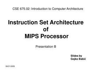
CSE 675.02: Introduction to Computer Architecture. Instruction Set Architecture of MIPS Processor Presentation B. Slides by Gojko Babi ć. MIPS Processor. M. e. m. o. r. y. C. P. U. C. o. p. r. o. c. e. s. s. o. r. 1. (. F. P. U. ). R. e. g. i. s. t. e. r. s.

Instruction Set Architecture of MIPS Processor Presentation B
E N D
Presentation Transcript
CSE 675.02: Introduction to Computer Architecture Instruction Set Architectureof MIPS ProcessorPresentation B Slides by Gojko Babić
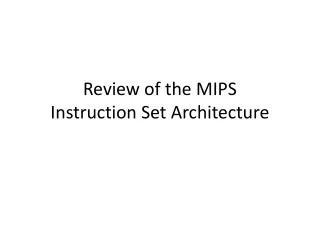
MIPS Processor M e m o r y C P U C o p r o c e s s o r 1 ( F P U ) R e g i s t e r s R e g i s t e r s $ 0 $ 0 Control $ 3 1 $ 3 1 r i t h m e t i c M u l t i p l y A Logic unit d i v i d e A r i t h m e t i c Prog. Counter u n i t L o H i C o p r o c e s s o r 0 ( t r a p s a n d m e m o r y ) R e g i s t e r s B a d V A d d r C a u s e S t a t u s E P C Figure A.10.1 Presentation B
MIPS Registers –32 32-bit general purpose registers – GPRs (r0 – r31); • CPU: r0 has fixed value of zero. Attempt to writing into r0 is not illegal, but its value will not change; • two 32-bit registers – Hi & Lo, hold results of integer • multiply and divide • 32-bit program counter – PC; • Floating Point Processor– FPU(Coprocessor 1 – CP1): –32 32-bit floating point registers – FPRs (f0 – f31); –five control registers; Presentation B
MIPS Registers (continued) • Coprocessor 0 – CP0 is incorporated on the MIPS CPU chip • and it provides functions necessary to support operating • system: exception handling, memory management scheduling • and control of critical resources. • Coprocessor 0 (CP0) registers(partial list): – Status register (CP0reg12) – processor status and control; –Cause register (CP0reg13) – cause of the most recent exception; –EPC register (CP0reg14) – program counter at the last exception; • BadVAddr register (CP0reg08) – the address for the most • recent address related exception; Presentation B
MIPS Data Types – 32-bit (unsigned or 2’s complement) integers, • MIPS operates on: – 32-bit (single precision floating point) real numbers, – 64-bit (double precision floating point) real numbers; • bytes and half words loaded into GPRs are either zero or sign • bit expanded to fill the 32 bits; • only 32-bit units can be loaded into FPRs; 32-bit real numbers • are stored in even numbered FPRs. • 64-bit real numbers are stored in two consecutive FPRs, • starting with even-numbered register. Presentation B
MIPS arithmetic • All instructions have 3 operands • Operand order is fixed (destination first)Example: C code: a = b + c MIPS ‘code’: add a, b, c “The natural number of operands for an operation like addition is three…requiring every instruction to have exactly three operands, no more and no less, conforms to the philosophy of keeping the hardware simple”
MIPS arithmetic • Design Principle: simplicity favors regularity. • Of course this complicates some things... C code: a = b + c + d; MIPS code: add a, b, c add a, a, d • Operands must be registers, only 32 registers provided • Each register contains 32 bits • Design Principle: smaller is faster. Why?
Control Input Memory Datapath Output Processor I/O Registers vs. Memory • Arithmetic instructions operands must be registers, — only 32 registers provided • Compiler associates variables with registers • What about programs with lots of variables
0 8 bits of data 1 8 bits of data 2 8 bits of data 3 8 bits of data 4 8 bits of data 5 8 bits of data 6 8 bits of data ... Memory Organization • Viewed as a large, single-dimension array, with an address. • A memory address is an index into the array • "Byte addressing" means that the index points to a byte of memory.
MIPS Addressing Modes • register addressing; • immediate addressing; • only one memory data addressing: –register content plus offset (register indexed); • since r0 always contains value 0: –r0 + offset absolute addressing; • offset = 0 register indirect; • MIPS supports byte addressability: –it means that a byte is the smallest unit with its address; • MIPS supports32-bit addresses: • it means that an address is given as 32-bit unsigned • integer; Presentation B
0 32 bits of data 4 32 bits of data 8 32 bits of data 12 32 bits of data ... Memory Organization • Bytes are nice, but most data items use larger "words" • For MIPS, a word is 32 bits or 4 bytes. • 232 bytes with byte addresses from 0 to 232-1 • 230 words with byte addresses 0, 4, 8, ... 232-4 • Words are aligned i.e., what are the least 2 significant bits of a word address? Registers hold 32 bits of data
MIPS Alignment • MIPS restricts memory accesses to be aligned as follows: – 32-bit word has to start at byte address that is multiple of 4; 32-bit word at address 4n includes four bytes with addresses 4n, 4n+1, 4n+2, and 4n+3. – 16-bit half word has to start at byte address that is multiple of 2; 16-bit word at address 2n includes two bytes with addresses 2n and 2n+1. Presentation B
MIPS Instructions • 32-bit fixed format instruction and 3 formats; • register – registerand register-immediate computational • instructions; • single address mode for load/store instructions: – register content + offset (called base addressing); • simple branch conditions; • –branch instructions use PC relative addressing; • – branch address = [PC] + 4 + 4×offset • jump instructions with: • –28-bit addresses (jumps inside 256 megabyte regions), • or • –absolute 32-bit addresses. Presentation B
Our First Example • Can we figure out the code? Guess!!! swap(int v[], int k); { int temp; temp = v[k] v[k] = v[k+1]; v[k+1] = temp; } swap: muli $2, $5, 4 add $2, $4, $2 lw $15, 0($2) lw $16, 4($2) sw $16, 0($2) sw $15, 4($2) jr $31
MIPS Instruction (continued) • Instructions that move data: • load to register from memory, • store from register to memory, • move between registers in same and different coprocessors • ALU integer instructions, • Floating point instructions, • Control-related instructions, • Special control-related instructions. Presentation B
Processor Memory Stored Program Concept • Instructions are bits • Programs are stored in memory — to be read or written just like data • Fetch & Execute Cycle • Instructions are fetched and put into a special register • Bits in the register "control" the subsequent actions • Fetch the “next” instruction and continue memory for data, programs, compilers, editors, etc.
/ft /offset /ft /fs /fd and fd fs funct ft jump_target MIPS Instruction Layout • MIPS instructions are an example of fixed field decoding Presentation B
CPU Load & Store Instructions • lw rt, offset(rs) ; load 32-bits: • Regs[rt] Mem [offset+Regs[rs]] • sw rt, offset(rs) ; store 32-bits: • Mem [offset+Regs[rs]] Regs[rt] • lb rt, offset(rs) ; load 8-bits (byte): • Regs[rt] 24-bit sign-extend || Mem [offset+Regs[rs]] Note: || means concatenation. • lbu rt, offset(rs) ; load 8-bits (byte) unsigned: • Regs[rt] 24-bit zero-extend || Mem [offset+Regs[rs]] • sh rt, offset(rs) ; store 16-bits: • Mem [offset+Regs[rs]] Regs[rt] • (16 least significant bits taken from the register) Plus: sb, lh, &lhu Presentation B
FP Load, Store & Move Instructions • lwc1 ft, offset(rs) ; load into FP register: • Regs[ft] Mem [offset+Regs[rs]] • swc1 ft, offset(rs) ; store from FP register: • Mem [offset+Regs[rs]] Regs[ft] • mov.d fd, fs ; move FP double precision between FPRs: • Regs[fd] || Regs[fd+1] Regs[fs] || Regs[fs+1] • mov.s fd, fs ; move FP single precision between FPRs: • Regs[fd] Regs[fs] Presentation B
Move Instructions • mfc1 rt, fs ; move from FPU to CPU: Regs[rt] Regs[fs] • mtc1 rt, fs ; move from CPU to FPU: Regs[fs] Regs[rt] • mfc0 rt, rd ; move from CP0 to CPU: Regs[rt] CP0Regs[rd] • mtc0 rt, rd ; move from CPU to CP0: CP0Regs[rd] Regs[rt] • mfhi rd ; move from Hi: Regs[rd] Hi; • mflo rd ; move from Lo: Regs[rd] Lo; Presentation B
ALU Integer Instructions • add rd, rs, rt ; add integer@: Regs[rd] Regs[rs] + Regs[rt] Note: Instructions flagged by @ may cause an arithmetic exception. • addi rt, rs, immediate ; add immediate integer@: • Regs[rt] Regs[rs] + 16-bit sign-extend || immediate • and rd, rs, rt ; bit-wise AND 32 bits: • Regs[rd] Regs[rs] AND Regs[rt] • andi rt, rs, immediate ; bit-wise AND immediate 32 bits: • Regs[rt] Regs[rs] AND 16-bit zero-extend || immediate • slt rd, rs, rt ; set less than integer: • if (Regs[rs] < Regs[rt]) then Regs[rd] 1 else Regs[rd] 0 Presentation B
ALU Integer Instructions (continued) • mul rs, rt ; multiply integer: Hi || Lo Regs[rs] × Regs[rt] • Note: mul does not generate an arithmetic exception, since • a storage for the result is always sufficiently large. • div rs, rt ; divide integer: Lo Regs[rs] / Regs[rt] • Hi Regs[rs] mod Regs[rt] • Note: div does not generate an arithmetic exception and • software should test for zero divisor. • sll rd, rt, shamt ; shift left logical: • Regs[rd] Regs[rt] << shamt • lui rt, immediate ; load upper immediate: • Regs[rt] immediate || 16 zero-bits Presentation B
ALU Integer Instructions (continued) • addu rd, rs, rt ; add unsigned integer: • Regs[rd] Regs[rs] + Regs[rt] • Instructions addu, addiu,subu, mulu, divu,sltu, and sltiu operate on unsigned numbers and these instructions do not trap on overflow. They are appropriate for unsigned arithmetic, such as address arithmetic, or in integer arithmetic environment that ignores overflow, such as C language arithmetic. Note: This instruction does not cause an arithmetic exception. Plus: addiu, sub@, subu, mulu, divu,or, ori, xor, xori, nor, slti, sltu, sltiu, srl, sra Presentation B
Arithmetic FP Instructions • add.d fd, fs, ft ; FP double precision add: • Regs[fd]||Regs[fd+1] • Regs[fs]||Regs[fs+1]+ Regs[ft]||Regs[ft+1] • mul.s fd, fs, ft ; FP single precision multiply: • Regs[fd] Regs[fs] × Regs[ft] Plus: add.s, sub.d, sub.s, mul.d,div.d, div.s, several convert floating point to/from integer instructions, several compare instructions. Note: Any of instructions above may cause FP exception. All instructions presented so far, in addition, increment the program counter PC by 4, i.e. PC [PC] + 4 Presentation B
Control Related Instructions - Jumps • jr rs ; jump register: PC Regs[rs] • jalr rs,rd ; jump and link register: • Regs[rd] [PC]+4; PC Regs[rs] • j jump_target ; jump inside 256 MB region: • PC low order 28 bits jump_target || 2 zero-bits • jal jump_target ; jump inside 256 MB region and link: • Regs[31] [PC]+4 • PC low order 28 bits jump_target || 2 zero-bits Presentation B
Control Related Instructions - Branches • beq rs, rt, offset ; branch on equal: • if (Regs[rs] = Regs[rt]) • then PC [PC]+4+ 14-bit sign extend || offset || 2 zero-bits • else PC[PC]+4 • bne rs, rt, offset ; branch on not equal: • if (Regs[rs] != Regs[rt]) • then PC[PC]+4+ 14-bit sign extend || offset || 2 zero-bits • else PC[PC]+4 • bgez rs, offset ; branch on greater or equal zero: • if (Regs[rs] ≥ 0) • then PC[PC]+4+ 14-bit sign-extend || offset || 2 zero-bits • else PC[PC]+4 Plus: bgtz, blez, bltz Presentation B
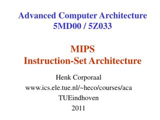
Illustration of MIPS Addressing Modes 1 . I m m e d i a t e a d d r e s s i n g o p r s r t I m m e d i a t e 2 . R e g i s t e r a d d r e s s i n g o p r s r t r d . . . f u n c t R e g i s t e r s R e g i s t e r 3 . B a s e a d d r e s s i n g M e m o r y o p r s r t A d d r e s s + B y t e H a l f w o r d W o r d R e g i s t e r 4 . P C - r e l a t i v e a d d r e s s i n g M e m o r y o p r s r t A d d r e s s + W o r d P C 5 . P s e u d o d i r e c t a d d r e s s i n g M e m o r y o p A d d r e s s W o r d P C offset offset jump_target Figure 2.24 Presentation B
Special Control - Related Instructions • syscall ; to cause a syscall exception • Encoding: 000000 00000000000000000000 001100 • break ; to cause a break exception • Encoding: 000000 00000000000000000000 001101 • teq rs, rt ; trap exception if equal:if (Regs[rs] == Regs[rt]) • then trap exception • tlti rs, immediate ; trap exception if less than immediate: • if (Regs[rs] < 48-bit sign-extend || immediate • then trap exception • eret ; return from exception Plus: several additional conditional trap instructions Presentation B
CPU Modes and Address Spaces There are two processor (CPU) modes of operation: • Kernel (Supervisor) Mode and • User Mode The processor is in Kernel Mode when CPU mode bit in Status register is set to one. The processor enters Kernel Mode at power-up, or as result of an interrupt, exception, or error. The processor leaves Kernel Mode and enters User Mode when the CPU mode bit is set to zero (by some instruction). Memory address space is divided in two ranges (simplified): • User address space – addresses in the range [0 –7FFFFFFF16] • Kernel address space – addresses in the range [8000000016– FFFFFFFF16] Presentation B
Privilege Instructions When operating in User Mode, processor has access only to the CPU and FPU registers, while when operating in Kernel Mode, processor has access to the full capabilities of processor including CP0 registers. Privileged instructions can not be executed when the processor is in User mode, i.e. they can be executed only when the processor is in Kernel mode • Examples of MIPS privileged instructions: • any instruction that accesses Kernel address space, • mfc0 – move word from CP0 to CPU, • mtc0 – move word to CP0 from CPU, • lwc0 – load (from memory) word into CP0, • swc0 – store (into memory) word from CP0. Presentation B
MIPS Exceptions: A Subset There are four sets of causes for an exception. A. Exceptions caused by hardware malfunctioning: • Machine Check: Processor detects internal inconsistency; • Bus Error: on a load or store instruction, or instruction fetch; • B. Exceptions caused by some external causes (to the processor): • Reset: A signal asserted on the appropriate pin; • NMI: Non-maskable interrupt – serious hardware problems • Hardware Interrupts: Six hardware interrupt requests can be • made via asserting signal on any of 6 external pins. • Hardware interrupts can be masked by setting appropriate bits • in Status register; Presentation B
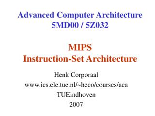
Exceptions by External Causes Reset IRQ1 NMI Presentation B
MIPS Exceptions: A Subset (continued) C. Exceptions that occur as result of instruction problems: • Address Error: a reference to a nonexistent memory segment, • or a reference to Kernel address space from User Mode; • Reserved Instruction: A undefined opcode field (or privileged • instruction in User mode) is executed; • Integer Overflow: An integer instruction results in a 2’s • complement overflow; • Floating Point Error: FPU signals one of its exceptions, e.g. • divide by zero, overflow, and underflow) • D. Exceptions caused by executions of special instructions: • Syscall: A Syscall instruction executed; • Break: A Break instruction executed; • Trap: A condition tested by a trap instruction is true;
MIPS Exception Processing When any of the exceptions previously listed occur, the MIPS processor processes the exception in the following 3 steps: Step 1. • EPC register gets a value equal to either: – address of a faulty instruction if the instruction itself caused exception (e.g. address error, reserved instruction) or detected hardware malfunctioning (e.g. bus error), – address of the next instructions which would have been executed, in all other cases. Additionally, in the case of the address error, BadVAddr register gets value of the invalid address. Presentation B
MIPS Exception Processing (continued) Step 2. (Simplified) • PC 8000018016 – next instruction executed is at the location 8000018016 • Cause register a code of the exception • – Each exception has its code, e.g.: • hardware interrupt = 0 • illegal memory address (load/fatch or store) = 4 or 5 • bus error (fetch or load/store)= 6 or 7 • syscall instruction execution = 8 • illegal op-code, i.e. reserved or undefined op-code= 10 • integer overflow = 12 • Floating point exception = 15 Step 3. • Processor is now in Kernel mode, i.e. CPU mode bit 1; Presentation B
Exception/Interrupt/Fault kernel user set user mode Dual-Mode of CPU Operation • CPU mode bit added to computer hardware to indicate the current CPU mode: 1 (=kernel) or 0 (=user). • When an exception or interrupt or fault occurs CPU hardware switches to the kernel mode. Privileged instructions can be executed only in kernel mode. Presentation B
Problem: OS loads the exception handling routine at the address 8100 000816. What else should be done so this routine is activated each time an exception happens? Your solution should include instructions. • Answer: Memory location 8000018016 should contain instruction j 40000216i.e. mem location 80000180 000010 00 0100 0000 0000 0000 0000 0010 j 0 4 0 0 0 0 2 • Effect of j instruction: PC [PC31..28] || [I25..0] || 02 • PC 1000 0001 0000 0000 0000 0000 0000 1000 8 1 0 0 0 0 0 8 Presentation B
Comments: • sll instruction is noop instruction • Add srav, srlv, sllv • mention two branch and link instructions • consider adding few fp instructions. Presentation B