Download
1 / 38
1.45k likes | 6.34k Views
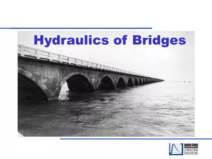
Hydraulics of Bridges. Objective. To understand: Nature of flow transitions through bridges, How to model a bridge, and Available bridge hydraulic methods. Topics Flow transitions through bridges Cross section locations Ineffective flow Contraction/Expansion losses

E N D
Objective To understand: • Nature of flow transitions through bridges, • How to model a bridge, and • Available bridge hydraulic methods. Topics • Flow transitions through bridges • Cross section locations • Ineffective flow • Contraction/Expansion losses • Hydraulic computations through bridges
Cross Section 1 • Cross Section 1 is located sufficiently downstream from the structure so that the flow is not affected by the structure (i.e. the flow has fully expanded). • If the distance between cross section 1 and 2 is too great for accurate friction loss calculations, then intermediate cross sections should be entered with ineffective flow areas defined.
Notes • b/B is the ratio of the bridge opening width to the total floodplain width, nob is the Manning n value for the overbank, nc is the n value for the main channel, and S is the longitudinal slope. • The values in the interior of the table are the ranges of the expansion ratio. For each range, the higher value is typically associated with a higher discharge. • The expansion ratio should not exceed 4:1, nor should it be less than 0.5:1 unless there is site-specific field information to substantiate such values.
Cross Section 2 • Cross section 2 is located immediately downstream from the bridge (i.e. a short distance, normally placed at the toe of the embankment). • This cross section should represent the effective flow area just outside the bridge and embankment. • Ineffective flow areas are normally used at this cross section.
Cross Section 3 • Cross section 3 should be located just upstream from the bridge (i.e. a short distance, normally located at the toe of the embankment). • This cross section should represent the effective flow area just outside the bridge and the embankment. • Ineffective flow areas are normally used at this cross section.
Cross Sections BU and BD • For bridge hydraulic computations, the program automatically formulates two additional cross sections inside of the bridge structure. • The geometry inside of the bridge is a combination of the bounding cross sections (Sections 2 and 3) and the bridge geometry. • These cross sections can be edited from the bridge/culvert editor.
Cross Section 4 • Cross section 4 is an upstream cross section where the flow lines are approximately parallel and the cross section is fully effective. • If the distance between cross section 3 and 4 is too great for accurate friction loss calculations, intermediate cross sections should be entered with ineffective flow areas defined.
Contraction Coefficient Coefficients ranged from 0.1 to 0.5 The mean was 0.12 The data of this study did not lend itself to regression of the contraction coefficient values. For nearly all of the cases the computed value was 0.1.
Contraction coefficients, special cases • The table above presents recommended ranges of the contraction coefficient for various degrees of constriction, for use in the absence of calibration information. • Highly skewed bridge crossings and bridges at locations of sharp curvature in the floodplain were not addressed in the study. • However, these recommendations may be applicable.
Ineffective Area Option Use Bridge Editor • Adjust lateral distance for bounding sections, based on distance from bridge • Define elevations based on top on when flow will overtop the bridge.
Review Bridge Flow Solution • Bridge Only shows all profile results • Review the bridge solutions and weir flow • Check continuity upstream and down from bridge to ensure “balanced” solution
Six Section Bridge Table Does the bridge solution check with cross-section solution?
Hydraulic Computations Through the Bridge The bridge routines in HEC-RAS have the ability to model: • Low Flow (Class A, B, and C) • Low flow and weir flow • Pressure flow (orifice or sluice gate types) • Pressure and weir flow • Highly submerged flows (energy equation)
Low-Flow computations Momentum is used to determine Class A, B or C • Class A - If the momentum downstream is greater than the critical depth momentum inside the bridge, the flow is considered subcritical. • Class B - If the momentum downstream is less than the momentum at critical depth, then it is assumed that the flow will pass through critical depth and a hydraulic jump will occur downstream. • Class C - The profile is considered completely supercritical through the bridge.
Class A Low-Flow Methods • All methods use Standard Step calculations for the transition sections (1 to 2 and 3 to 4). • Four methods are available to compute bridge hydraulic losses (Between Sections 2 to 3): • Energy Equation (standard step method) • Momentum Balance • Yarnell Equation • WSPRO low-flow model
Energy Method (Standard Step) BU BD 2
Yarnell Equation Where: H3-2 = The drop in water surface from section 3 to 2 K = Yarnell’s pier shape coefficient = Ratio of velocity head to depth at section 2 = Obstructed area of the piers divided by the total unobstructed area V2 = Velocity at cross section 2 The Yarnell eq. provides hydraulic information only at sections 2 and 3.
Yarnell’s Pier Coefficient, K Pier Shape Yarnell K Coefficient Semi-circularnose and tail 0.90 Twin-cylinder piers with connecting diaphragm 0.95 Twin-cylinder piers without diaphragm 1.05 90 degree triangular nose and tail 1.05 Square nose and tail 1.25 Ten pile trestle bent 2.50
FHWA WSPRO Method Energy balance from section 1 to 4: Where: Z = Bed invert elevations Y = Water surface elevations V = Average velocity hf = Friction losses he = Expansion losses from section 1 to 2 The WSPRO method computes the water surface profile through a bridge by solving the energy equation is steps from d/s to u/s.
Floating Debris can be added • Floating Debris- checked will provide for Pier 1 debris input. • Set for all - defines for all piers. • Debris rises with water up to the top of the pier.
Class B and C Low-flow Methods Two methods are available: Momentum - the default method. (With irregular cross-section data and rapidly changing water surface elevation, the estimate of bed slope can be erratic. Therefore, the weight component is automatically turned off for Class B flow.) Energy - During Class B flow, a dramatic change in depth can occur with resulting large changes in velocity head. Contraction and Expansion energy losses may be overestimated with “traditional” contraction and expansion coefficients.
High Flow Bridge Methods Energy Method - The area of the deck is subtracted and additional wetted perimeter is added. The water surface elevation represents the hydraulic grade line. • This method does not account for the shape of the entrance or piers. • Conveyance is calculated treating the bridge as a normal cross section, including flow over the roadway.
High Flow Methods, continued • Pressure and Weir Method - Treats the flow as two separate components. • Flow through the opening is pressure flow: • Upstream end submerged – sluice gate equation • Both ends submerged – orifice equation • Flow over the roadway is weir flow, with tailwater submergence. (Energy method for high tailwater)
Cd For Sluice Gate Pressure Flow The discharge coefficient Cd, can vary depending upon the depth of water upstream, ranging in values from 0.35 to 0.5. A value of 0.5 is commonly used.
Orifice Pressure Flow Typical values for the discharge coefficient C range from 0.7 to 0.9. A value of 0.8 is used for most bridges.
Weir Flow Computations The approach velocity is included by using the energy grade line elevation instead of the upstream water surface elevation for computing the head, H.
Weir Flow Submergence The program will automatically reduce the weir coefficient to account for submergence on the weir.
Combination Flow Low Flow and Weir Flow • Iterative solution for upstream energy • Can be used with any of the low flow methods, except the momentum method
Recap Topics covered: • Nature of flow transitions through bridges • How to model a bridge • Available bridge hydraulic methods • Flow transitions through bridges • Cross section locations • Ineffective flow and contraction/expansion losses