Download
1 / 12

E N D
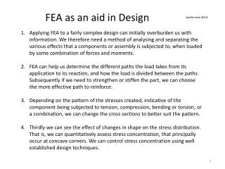
FEA as an aid in Design Andrei lozzi 2014 Applying FEA to a fairly complex design can initially overburden us with information. We therefore need a method of analysing and separating the various effects that a components or assembly is subjected to, when loaded by some combination of forces and moments. FEA can help us determine the different paths the load takes from its application to its reaction, and how the load is divided between the paths. Subsequently if we need to strengthen or stiffen the part, we can choose the more effective path to reinforce. Depending on the pattern of the stresses created, indicative of the component being subjected to tension, compression, bending or torsion, or a combination, we can change the cross sections to better suit the pattern. Thirdly we can see the effect of changes in shape on the stress distribution. That is, we can quantitatively assess stress concentration, that principally occur at concave corners. We can control stress concentration using well established design techniques.
A single load path from the point of application of a load, to the point where reaction to that load takes place. Point where the load is applied to the component. The ‘load’ may be some combination of forces and moments. If at all possible, the most effective load path is a straight line from the load to the reaction. The component is presumed to be contained within this envelope Point or points where the reaction to the load takes place
A sequence of load paths from the point of application of a load, to the point where reaction to that load takes place. Here the path is not the shortest, but is made up of two indirect paths. The stresses created within those paths will be some complex combination due to bending, shear, torsion and other. This may make arriving at an effective overall shape of the component somewhat difficult to conceive.
Multiple load paths from the point of application of a load, to the reaction. In general, the load will be shared between the paths according to their relative stiffness. Reinforcing the less stiff path will have a lesser outcome than augmenting the more rigid one.
A simple example of parallel load paths. Here for the spring at left, we can say because it has fewer coils, of thicker wire and of smaller coil diameter, will be stiffer than the one at right. Let the relative stiffness be: KL= 10 KR If the applied force F causes an extension of Δ, the force carried by the left and right springs are: FR= ΔKR FL = ΔKL = Δ10 KR Where FT = FL+ FR= Δ11KR The fraction of the force carried by either spring is proportional to the relative stiffness of that spring. FL / FT=10 / 11 FR / FT = 1/ 11 The applied external force is divided between the two load paths in proportion to the ratio of their stiffness to the total stiffness. FT FT
A force is shown applied to an edge of the ‘angle’ L section at right, and reproduced in plan view below l1 l2 l1 l2 The applied force is somehow divided between the two legs of the L section - l1 &l2 . What resistance does that force meet ? The aligned leg - l1 has to bend about the neutral axis shown, it has a relatively large second moment of area I1, hence it will be stiff. Leg l2 has a small I2 hence will be relatively flexible.
An Example of reinforcing the more flexible load path on the stiffness and stress level of a part. Here a web has been added to the more flexible of the two legs of this ‘angle’ section. We compare here the stress and deflection with a similar connection without the web shown here vMises stress at the free edge has increased from 65 to 70 N/mm^2. Stress have been reduced from 87 to 73 N/mm^2 at the outer corner. Max deflection has been reduced from 0.494 to 0.447 mm
An Example of reinforcing the more rigid load path on the stiffness and stress level of a part. Here a web has been added to the more rigid of the two legs of this ‘angle’ section. As before we compare here the stress and deflection with a similar connection without this web. vMisesstress is reduced from 87 to 70 N/mm^2 at the outer corner. Stress at the free edge has increased from 65 to 28 N/mm^2. Max deflection has been reduced from 0.494 to 0.307 mm.
We make the following observations: Placing the webs in just about the least advantageous position reduce deflection but by only 10%. Placing similar sizes webs in a relatively advantageous position reduced deflection by 40%. Placing the hold-down bolt holes, close to the most heavily loaded welds, reduces deflection by a further 10%.
In general, to reduce stress concentration, add material where the stress is high, and remove material where the stress is low – very simple. Examples of the means that may be used to control stress concentration. In (a) and (b) above the large fillet radii and notches in the low stress areas, help to smooth the force field (stress levels). Adding notched in the high stress areas has the opposite effect. At left the additional small holes before and after the large one, helps to redistribute stress as if a smoother elliptical hole were present.
A real example – This ‘wheel upright’ is connected to the chassis by the 4 bolt holes at top and the 2 at the bottom. The wheel is supported by 2 bearings in the centre. The wheel transmits forces and moments through those bearings and a forces come from the brake calliper. All these loads are then passed on to the chassis. The upright shown here, is made in two halves in Al alloy, welded together at the mid-plane and is hollow, about 1 -2 mm thick.
Stress and deflection is shown here. What would you do to principally minimise mass while reducing deflection