Download
1 / 18
180 likes | 352 Views
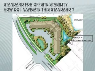
Standard for offsite stability how do I navigate this standard ?. Detention / Infiltration Structure. Figure 21–1 Point Discharge and Downstream Stability Analysis Procedure . Where is the stability concern for our site?. Pre-Development Peak Flows: 2 Yr. – 10.00 cfs 10 Yr. – 15.00 cfs

E N D
Standard for offsite stabilityhow do I navigate this standard ? Detention / Infiltration Structure
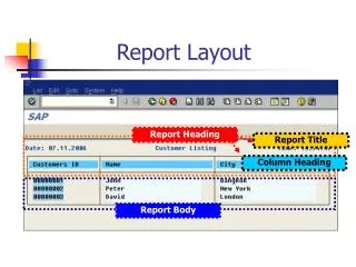
Figure 21–1 Point Discharge and Downstream Stability Analysis Procedure
Pre-Development Peak Flows: 2 Yr. – 10.00 cfs 10 Yr. – 15.00 cfs Allowable Post-Development Peak Flows: 2 Yr. – 10.00 cfs x 0.50 = 5.00 cfs 10 Yr. – 15.00 cfs x 0.75 = 11.25 cfs sample site analysis
Post-Development Detention Basin Discharge: Scenario No. 1 – Infiltration Basin 2 Yr. – 0.00 cfs 10 Yr. – 0.00 cfs - 100 % Infiltration – Therefore the basin must be flood routed under the following criteria: • Infiltration has failed • - The basin is filled to the crest elevation of the primary spillway or the emergency spillway • - A ten year storm event occurs What happens? Sample site analysis continued:
Infiltration basin scenario 1 Must analyze as follows: Post – Development Peak Discharges with failed infiltration and the basin filled to the crest of the Emergency Spillway: (Flood Routed Outflows) 2 Yr. – 3.50 cfs 10 Yr. – 8.75 cfs Pre-Development Peak Flows: 2 Yr. – 10.00 cfs 10 Yr. – 15.00 cfs Allowable Post-Development Peak Flows (With Reductions): 2 Yr. – 10.00 cfs x 0.50 = 5.00 cfs 10 Yr. – 15.00 cfs x 0.75 = 11.25 cfs
Infiltration basin scenario no. 2 Post – Development Peak Discharges with failed infiltration and the basin filled to the crest of the Emergency Spillway: (Flood Routed Flows) 2 Yr. – 12.00 cfs 10 Yr. – 22.00 cfs Must construct a stable conveyance! 10 cfs for a 25 yr. storm! Pre-Development Peak Flows: 2 Yr. – 10.00 cfs 10 Yr. – 15.00 cfs Allowable Post-Development Peak Flows: 2 Yr. – 10.00 cfs x 0.50 = 5.00 cfs 10 Yr. – 15.00 cfs x 0.75 = 11.25 cfs
Where there is no well defined channel, no sandy condition, no trees or brush to substantially concentrate the flows and it can be reasonably assumed that the flow will disperse over a broad area. The combinations of slopes and soils in table 21-1 and the following criteria are considered stable for flows of 10cfs or less for a 25 year, 24hr design storm. Table 21-1 Non-Erosive Velocities for Point Discharges Maximum Stable Slope for Point Discharges for Various Soils Soil Type Maximum Slope (%) Sands1.8 Sandy loam 2.0 Silt loam, loam 2.5 Sandy clay loam 3.5 Clay loam 5.0 Graded loam to gravel 8.0 Stability Criteria (in conjunction with table 21-1) i. The maximum discharge rate shall be 10 cfs or less for the twenty-five (25) year storm. ii. Multiple outlets may be utilized to reduce individual outlet flow rates to levels below the thresholds noted above. Outlets should be spaced no closer than 50 ft horizontally to avoid re-mixing of flows. iii. Flow over the outlet area shall be less than 0.5 cfs/ft. Designers shall not design excessive widths which will cause flows to concentrate. iv. Conduit outlet protection shall be provided in accordance with that Standard and may include: flat aprons, preformed scour holes, impact basins, stilling wells, plunge pools, etc. Level spreaders are not an acceptable design. v. Topography shows broad uniform outlet area where flows will not concentrate. vi. Discharge locations shall contain perennial, erosion resistant vegetation. vii. Peak discharge velocities (in the last pipe section) do not exceed 2 fps. viii. The maximum length of slope below the outlet(s) is 100 feet. Table 21-1
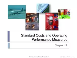
50 ft. minimum Multiple basin outlets
Standard detention basin example with a defined receiving waterway Pre – Development Site Peak Discharges 2 Yr – 22.00 cfs 10 Yr – 31.00 cfs Post – Development Site Peak Discharges 2 Yr – 32.00 cfs 10 Yr – 44.50 cfs Channel Analysis at Point of Discharge: 2 Yr. Channel Velocity – 5.45 fps 10 Yr. Channel Velocity – 7.88 fps (Based on HEC-RAS) Allowable Channel Velocities based on Standard for Channel Stabilization: Clay Loam Soil = 5.0 fps
Modify channel to a stable condition Here is what the existing channel looks like. Here is what the new channel will look like.