Download
1 / 12
120 likes | 138 Views
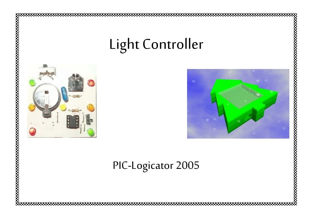
Light Controller PICAXE PIC-Logicator 2005. Light Controller. PCB Wizard. Actual Circuit. Space for LDR and resistor if needed. Solder Side. Artwork Silkscreen. Solder Side. NB 4 wire Bridges are also needed to make the circuit work.

E N D
Light Controller PICAXE PIC-Logicator 2005
Light Controller PCB Wizard Actual Circuit Space for LDR and resistor if needed Solder Side Artwork Silkscreen
Solder Side NB 4 wire Bridges are also needed to make the circuit work 4 wire bridges will also be needed to complete circuit Component Side
Components in Red (LDR and 220Ώ Resistor are not necessary to programme the light circuit. They have been included as an option to push more able pupils. A spaces have been left for them on the circuit board
Programming When programming remember that Outputs 0, 1 and 4 work in pairs while Output 2 has a single LED attached
11.80 305 x 475 145,825 60 x 50 3,000 145,825 3,000 48 (Full sheets) 11.80 48 (Round answer up) 0.25
Planning for making. Example and key words Key Words. PCB drill. Safety specs. Soldering station.Wire strippers. Long nose pliers. End snips.Solder. Soldering board. Electrical components.Battery holder. Switch. PCB. Capacitor. Light emitting diode. Resistor. Ventilation. Download socket Safety.PIC Chip. Resistor. CAD/CAM. CNC Machine. Foamed PVC. Lid/Base. Drill. Dr Stikka. Packaging. Quality. Silicone carbide paper.
Assembly 1. Thread the centre sections and backs onto a 3mm plastic tube using the pilot holes as guides. 3. Using a junior hacksaw cut off any excess pipe and you may want to drill holes to gain access to the on/off switch. 2. Glue the sections together using liquid solvent cement. Capillary action will suck the glue in along the joints. 4. Smooth the edges of the material using silicone carbide paper working your way up the grit size until a smooth edge finish is achieved. Make sure you do not wrap the paper around the sides since this will scratch the surface and spoil the finish of your material. 5. Smooth the edge of the front cover using silicone carbide paper and polish to a bright finish. 6. Apply 2 Stainless steel panhead Self-Tapping Screws to attach the cover to the case.
EVALUATION Use the following points to help you with your evaluation. * Explain the good and bad points of mass production. * In what way does your finished work answer the points of the design specification? * Use notes and diagrams to explain how you could improve your work. * What do others think of your finished work, including your folder? * What is the most important thing that you have learned? * What are the things that gave you most and least satisfaction in doing. * What problems did you have during making your product and how did you overcome them? * Did you manage your time effectively or not and in what way did you do this?