Download
1 / 32
320 likes | 363 Views
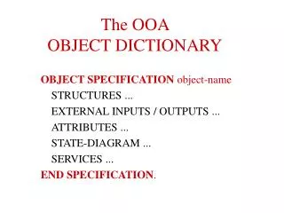
This article discusses the steps in the Object-Oriented Analysis (OOA) process, focusing on scenarios. It covers identifying classes, structures, generalization, aggregation, association, defining attributes, services, message passing, states and transitions. It also explains the concept of object dictionaries and provides examples of scenarios in OOA.

E N D
The OOA Process - II Scenarios
The Steps of OOA - Part 1 • Identify classes (objects) • Identify structures • Generalization (generalization-specialization, “ISA” relationship type) • Aggregation (whole – parts, “PART-OF” relationship type) • Association (relationship) • Define attributes ===> Static Object diagram ===> incomplete Object Dictionary
The Steps of OOA - Part 2 • Define services (operations) via scenarios • services per object • message passing between objects • coordination of message passing • states and transitions ===> Scenarios ===> complete Object Dictionary
OOA - Messages sender • Form the dynamic portion of the object diagram (scenarios) • Sent by • an object (instance) • via an active local service • Received by • an object (instance) • triggering the receiving service label receiver
A Message’s “Life-Cycle” • Connects to an object(object_id).service • Triggers execution of the receiving service • Carries input-parameters for the execution of the receiving service • Is able to transmit output-parameters back to the sending service
Message Specification • Scenarios (diagrams): • shown as bold or dotted line • labeled with the receiving service • parameters are optional • sequence number may be optional • Object dictionary: • exist only as elements of an object’s services • specified as part of the service specifications
Syntax for Message Specification • Typically similar to: SEND MESSAGE TO object (object_id).service (input-parameters, output-parameters) • object: name of an object class • service: name of a service in that object class • object_id: identifies selected instantiation ===> Complete Object Dictionary ===> Informal Scenarios Analysis
The division wants to compile a list of the prg. languages “spoken” in its departments. Division (2,N) (1,1) Programmer Department list of prog-lang. (3,N) (1,1) works-for
Division Alternative 1: Using output-parameters to get to the results. report prg-langs list prg-skills (wait for result) Programmer Department list prg-lang (wait for result) list prg-lang list prg-skills
Alternative 2: Using separate messages to transmit results. Division report prog-langs accept prg-lang accept prg-lang list prg-skills (do not wait for result) Programmer Department list prg-lang (do not wait for result) list prg-langs list prg-skills
OOA - Services • Exist only as elements of an object/class • Services model functionality: • data manipulation • control sequences • communication (using messages) • state transformation • interface handling
OOA - Services • No separate graphical representation (part of the class and object symbols) • Services can be • public or • private • Specified in the object dictionary
Attributes and Services • The data capsule principle • a service has access to all attributes of the local object • all services of an object share attributes as a global data area • a service provides access to attributes for other object.services (by accepting messages) • a service can have local variables
Services and Inheritance • Services are inherited in a classification hierarchy • Inheritance is mandatory • Multiple inheritance is possible => Position common services as high in the classification hierarchy as possible => Generic services (service overlay / polymorphism)
Employee Inheritance fill-in time-sheet prepare paycheck Manager Programmer fill-in time-sheet fill-in time-sheet list prg-langs
Scenarios • Show separate self-contained sequences (threads) of execution • Typically include: • objects • messages • (services) • (attributes) • Do usually not include • Structures • Can be represented by different UML diagrams
hire (2) Division create (1) Department Manager Programmer Scenario 1: “Open a new department” hire (3)
OOAD - Modeling Rememeber • Differentiation between static and dynamic diagrams • Usually • one static class diagram • multiple diagrams modeling system dynamics • possibly with different notations to capture specific dynamics • Everything is based on the common object dictionary • also called: model, class specifications, ... • diagrams are only views (or projections) of this common dictionary • diagrams have to be compatible with • the dictionary and • each other
Diagrams in UML • Requirements Diagrams (Use-Cases, Scenarios) • Class and Object diagrams – Static, structural view • Classes & Objects • Attributes • Methods • Structures • Association, Generalisation, Aggregation • Behavioral diagrams- dynamic view • Collaboration Diagrams • Sequence Diagrams • Statechart Diagrams • Activity Diagrams • Implementation diagrams • Component diagrams • Deployment diagrams ==> UML diagrams for representing “scenarios”
Sequence diagrams (1) • A sequence diagram shows a subset of the possible interactions between objects in a system. • context sensitive “slicing“ of all possible interactions • a view on the dynamics of the system • focus on timing of interaction • related operations can be deduced (less detail than in collaboration diagram) • messages seen very much as events • relations and attributes are not shown • Alternatives are • collaboration diagrams, activity diagrams, use cases • all have specific focus and strength
Sequence diagrams (2) • A sequence diagram is used to model • a snapshot of interactions (events) within a time-frame • a scenario, (partial) process or transaction • The diagram includes • objects (instances) • only objects involved in the scenario • all objects only by name • the “life-line” of an object: the dimension of time • the “focus of control” (Steuerungsfokus): marks the active, controlling object • messages • messages are seen very much like events • parameters & conditions in messages are possible but unusual • returns/responses to messages are usually modeled separately
message specification :obj1 :obj3 :obj2 msg_x ( ) t1 {t2 -t1 < delta} control focus response_x t2 msg_y ( ) contstraint response_y life-line Sequence diagrams - notation (1)
indirect recursion :obj1 :obj2 msg_x ( ) msg_y ( ) response_y response_x self delegation Sequence diagrams - notation (2)
create and delete objects :obj1 new ( ) msg_x ( ) response_x delete ( ) Sequence diagrams - notation (3) :obj2
:obj1 :obj3 :obj2 [cond1] msg_x1 ( ) [cond2]msg_x2 ( ) response_x1 response_x2 conditions and alternative life-lines Sequence diagrams - notation (4) msg_y ( ) response_y
message & parameters • - name of the message • - usually the name of the operation to be invoked in the receiving object • - usually not the full signature of the operation (check there) • - iteration can be modeled using * • result • - unusual; usually modeled using a separate arrow • - name of the result delivered by the message • condition • - boolean expression • - use with caution • - if many conditions are necessary, switch to activity diagrams Sequence diagrams - message (event) specification
1.1: pcPrice:=getPrice( ) :PersComp 1.1.1.*: getCost( ) 1: offer:=makeOffer(cid, pcid) 1.4: createOrder( ) :Shopping Cart :Component :OrderMgr :Order askForOffer( ) 1.2:getDiscountRate( pcPrice ) :Customer 1.3:getNickname( ) Collaboration diagrams • A collaboration diagram is used to model a snapshot of interactions between objects, forming a scenario.
Possible sequencediagram for the collaboration diagram on page 29 :Shopping Cart :Customer :OrderMgr :PersComp :Component askForOffer() makeOffer(cid,pcid) getprice() *getcost() pcPrice getDiscountRate (pcPrice) getNickname createOrder() :Order offer
Caller Operator Callee call number call ack ack transfer talk time Sequence diagrams - example (3): operator assistet call
user Account acct # balance sec-code state Translate: Collaboration Diagram 3-a Version 2.0 withdrw :Trans_ Collection trans_record :Savings_Acct :Atm atm # req_withdrw “parameter” acct# 1: withdrw (..) X 1.1: addElement (transaction)