Download
1 / 41
430 likes | 649 Views
Product Life Cycles and Sustainability. 34%. 34%. 2%. 2%. 14%. 14%. -2s. -3s. +2s. +3s. -1s. m. +1s. Product Life Cycles. Concept Design Manufacture Shipment and Installation Warranty Period Useful Life Failure and Repair Disposal. Product Life Cycles. Concept Design

E N D
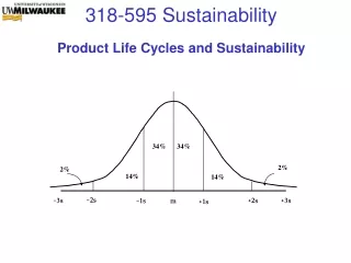
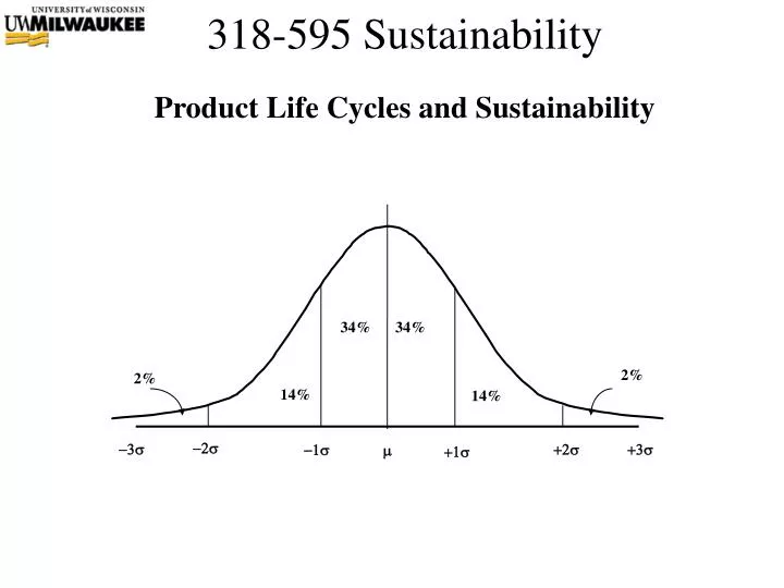
Product Life Cycles and Sustainability 34% 34% 2% 2% 14% 14% -2s -3s +2s +3s -1s m +1s
Product Life Cycles • Concept • Design • Manufacture • Shipment and Installation • Warranty Period • Useful Life • Failure and Repair • Disposal
Product Life Cycles • Concept • Design • Manufacture • Shipment and Installation • Warranty Period • Useful Life • Failure, Service & Repair • Disposal Traditional Design Eng Focus Traditional Mfg Eng Focus
Product Life Cycles • Concept • Design • Manufacture • Shipment and Installation • Warranty Period • Useful Life • Failure, Service & Repair • Disposal Traditional Design Eng Focus Traditional Mfg Eng Focus Life Cycle Product Focus
Customer Labeling: User Manual • Product Specifications • List Product Level Capabilities (Requirements) • Standard Requirements • Performance Requirements • Environmental incl Temperature, Humidity, etc • Mechanical Dimensions, Mass, Shock, etc • Control Inputs • Outputs including Displays • Interfaces including precise definition of connectors, signals • Complete Description of Operating Modes • Button or Menu Sequences for Clarity
User Manual • Safety and Regulatory Certifications • UL Safety Standards • IEC and CISPR EMC Standards • User Warnings • Limitations of Product by Demographics, Geographics • Cautions and Warnings • Compatibilities or Incompatibilities • Specific Label Applications or Misapplications • Safety Rules
User Manual • Operation …..How do you use the product? • Step Method (used for simple products) • Step 1, Step 2, …. etc • Menu Method • Show how to move to any given mode • When in mode, show all user screens or displays • Show/Describe all Possible User Inputs • Describe all Possible Outputs/Displays user may see
User Manual • Maintenance • Specified for a period of calander time, operational time or number cyclic operations • Describes what is to be calibrated, checked, replaced, etc • Test Procedures, Calibration Procedures, Replacement Procedures • Typical Replacements Include • Batteries • Sensors • Filters • Mechanical Wearout Components such as drive belts, pulleys, etc • Manual Section should show pictoral and textual replacment steps • Manual should indicate who should perform the maintenance (authorization, training level, etc) • Relationship to product warranty
User Manual • Service • Specified for repairs above and beyond normal maintenance • Service Strategies Include (Select 1 or more) • Field Repair by User • Requires service manual and replacement part depictions • Requires a concise list of replacement parts and procurement • Specialized Service Center • Requires specific replacement parts list • Specific testing equipment and skills • Factory Repair or Replacement • Still Requires replacement parts list documentation • Requires repair process chart (mimics mfg test processes) • Assembly/Dissassembly • Default-Disposal • Requires disposal strategy, No repair strategy • Must identify specific disposal procedures for ALL batteries
User Manual • Warranty (From Previous Lab) • Specified for a period of time or number of operations • Must specify how to exercise the warranty • Teams should show (in ppt slide) relationship between warranty period and reliability calculations • Reliability analysis yields F(1 warranty period) = % of population that will fail within 1 warranty period. Assign Cost/Failure. • Warranty Costs = $ Cost of Failures << 1% of total sales • MTBF under simplified conditions indicates when ~63% of population has failed. In general, Warranty Period << MTBF
User Manual • Other Sections/Elements • Digital Pictures • Ideal for Describing User Controls • Assembly/Dissassembly, Exploded Views • Correct operational waveforms • Common Troubleshooting • Problem/Symptom • Cause • Corrective Action
Sustainability Aspects: Obsolescence • Standardized Industry Life Cycle Definition • Standardized Statistical Prediction Tool • Component Life Parameters, u, s • For any given part you must consider; • Part Type and Functionality • Manufacturer(s) and number of sources • Part Technology and Process • Part Package
Sustainability 6 Std Component Production Life Phases Rate of Production • = Mean (Max) Sales of Unit Components per Unit Time s = One Standard Deviation in Production/Time or Sales/Time
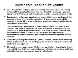
Production Life Cycle of a Component • Special Histogram of Production as Measure by Component Sales/Time (# shipped/time) • Concept Assumes Component Sales follow monotonically increasing to peak, then monotonically decreasing to obsolescence • Life Cycle is Measured Relative to Peak of Sales • +/- 1s from Peak = Mature Product • -1s to –2s from Peak = Growth Product • -2s to –3s from Peak = Introductory Product • +1s to +2s from Peak = Declining Product • +2s to +3s from Peak = Phase Out Product • +3s and higher from Peak = Obsolete Product
Statistics Application: Production Life Cycle of a Component Recall Area under curve = Percent Probability 34% 34% 2% 2% 14% 14% -2s -3s +2s +3s -1s m +1s Characterized by Two Parameters m and s2 Normal Distribution = N( m,s2 )
Sustainability Life Cycles of IC Process Voltages 2000 2010 2020 1980 1990
Sustainability Discrete RC, SMT Package Outlook Decreasing Power Rating Dominant Package by Year
Sustainability Aspects: Obsolescence • For each applicable component in your block BOM, perform a variance analysis • 1st Consider the part type: Find the u+(2.5)s, u+(3.5)s dates • 2nd Consider any applicable attributes • 3rd For each attribute find the u+(2.5)s, u+(3.5)s dates • Find the worst case u+(2.5)s, u+(3.5)s dates • Use u, s in years • +2s to +3s from Peak = Phase Out Product • +3s and higher from Peak = Obsolete Product • Create a separate BOM table of obsolescence analysis with above data • ID all parts above the 2.5s, Separately ID all above 3.5s Formulate Corrective Actions or Risk Mitigations Note: If you have a component that does not fit any category, ignore it for this analysis
Sustainability Aspects: Appendix Component Life Cycle Data Table • DOI = Date of First Introduction to Market • Note: Based on actual data but ALL numbers may not be realistic
Sustainability Aspects: Appendix Component Life Cycle Attribute Data Table
Waste Electrical and Electronic Equipment (WEEE)Restrictions on Hazardous Substances (RoHS) European Community Directives 2002/95/EC & 2002/96/EC Will impact global electronics industry (incl USA)
“This symbol indicates that the waste of electrical and electronic equipment must not be disposed as unsorted municipal waste and must be collected separately. Please contact t he manufacturer or other authorized disposal company to decommission your equipment.” WEEE Directive 2002/96/EC “on Waste Electrical and Electronic Equipment“ • Producers must take back waste electronic equipment from collection points • Financing: • Producers/Importers are responsible for financing and treatment of waste equipment from private households (which includes most small businesses) • Product sales can show a visible fee for up to 10 years • Producers and users others than private households may conclude agreements stipulating other financing methods • Products have to be marked with the brand of the producer, recycling symbol & date • Producers must provide specific disassembly information for treatment facilities • Targets are set in the directive for reuse, recovery and recycling (ex. Medical) • Producers/Importers have to be registered with local systems • Member states have to report on the targets; so record keeping required Labeling Must Include the WEEE Symbol and Guidance Info Date of manufacture: month / year Typical Guidance Statement for Industrial Equipment
WEEE Regulated Materials and Devices • 1) Polychlorinated biphenyls (PCB) containing capacitors in accordance with Council Directive 96/59/EC of 16 September 1996 on the disposal of polychlorinated biphenyls and polychlorinated terphenyls (PCB/PCT) (1). • 2) Mercury containing components, such as switches or backlighting lamps, • 3) Batteries Including, • Lithium batteries • Alkali-Manganese batteries • Dry cell batteries • Nickel-cadmium rechargeable batteries • Lead rechargeable batteries • Silver round cell batteries • 4) Printed circuit boards of mobile phones generally, and of other devices if the surface of the printed circuit board is greater than 10 square centimeters. • 5) Toner cartridges, liquid and pasty, as well as color toner. • 6) Plastic containingbrominated flame retardants. • 7) Asbestos waste and components which contain asbestos.
WEEE Regulated Materials and Devices • 8) Cathode ray tubes • 9) Refrigerant including chlorofluorocarbons, hydrochlorofluorocarbons, hydrofluorocarbons & hydrocarbons • 10) Gas discharge lamps such as halogen, neon, xenon, etc • 11) Liquid crystaldisplays (together with their casing where appropriate) of a surface greater than 100 square centimeters and all those back-lighted with gas discharge lamps • 12)External electric cables • 13)Components containingrefractory ceramic fibers as described in Commission Directive 97/69/EC of 5 December 1997 adapting to technical progress Council Directive 67/548/EEC relating to the classification, packaging and labeling of dangerous substances (2). • 14) Components containingradioactive substances (except components below exemption thresholds set in Art. 3 of and Annex I to Directive 96/29/Euratom of 13 May 1996 laying down basic safety standards for the protection of the health of workers and the general public against the dangers arising from ionizing radiation (3)) . • 15) Electrolytic capacitors containing substances of concern (height > 25 mm, diameter > 25 mm or proportionately similar volume) .
Member States can expand the equipment list Producers will be accountable for records of annual mass of each restricted substance shipped into each EC country But conflicts among accounting firms on how to reserve for WEEE obligations, some countries may charge up-front Firms may have to pay into a deposit system; and reserve for a contingent liability Some European wide associations being formed to manage WEEE But member states have strong incentive to keep all waste in their system to maximize fee income Definition of “producer” is problematic What happens if distributors ship equipment from one member state to another? Who is responsible as the “producer”? WEEE Implementation Difficulties
Recycling Passport Master Recycling Passport 03/2003 Edition: 1 Page 1 of 4 1 Editor / Department Model Type xxx ( Type Number File: ++49 89 6207-3681 / FAX: ++49 89 6207-7140 2003.03.04_rp neu.doc mailto:georg.karl.gk1@germany.agfa.com 1. General view of the device 8 6 5 4 11 2 7 3 12 9 10 1 13 WEEE requires special identification of waste for recycling or special handling Example: Agfa Copier (Operator Manual)
RHS Directive 2002/95/EC “on the Restriction of certain Hazardous Substances in Electrical and Electronic Equipment“ (ROHS) Requirements: Covered Equipment put on the market after July 1, 2006 is not allowed to contain (0.1% mass or less in homogenious materials, 0.01% or less for Hg): • Lead • Mercury • Cadmium • Hexavalent Chromium (used mostly for corrosion protection) • Polybrominated Biphenyls (PBB) or • Polybrominated Diphenyl ethers (PBDE) (flame retardants) Limited, but critical exemptions (medical devices for example)
2008 – Med Devices 2006 – Products/Industries • DI Products (X-Ray, MR, CT, etc.) • Patient Monitoring • EKG, Lab Eq, Dialysis • Large household appliances • Small household appliance • IT and telecommunications equipment • Consumer equipment • Lighting equipment • Electrical and electronic tools • Toys, leisure and sports equipment • Automatic dispensers Category Device Exemptions Expected to End Jul 1 ’08
AlloyComposition LiquidusTemp. (ºC) Reflow Temp. (ºC) MeltingRange#(ºC) Sn-37Pb (63% Tin, 37% Lead) 176-183 Sn-3.5Ag 221 240 – 250 Sn-0.7Cu 227 245 – 255 Sn-3.0Ag-0.5Cu* 220** 238 – 248 Sn-3.2Ag-0.5Cu 218 238 – 248 217-218 Sn-3.5Ag-0.75Cu* 218 238 – 248 Sn-3.8Ag-0.7Cu 220** 238 – 248 217-210 Sn-4.0Ag-0.5Cu 217-219 Sn-4.0Ag-1.0Cu* 220** 238 – 248 217-220 Sn-4.7Ag-1.7Cu* 244** 237 – 247 Sn-5Sb 232-240 Sn-0.2Ag-2Cu-0.8Sb* 285** 246 - 256 226-228% Sn-2.5Ag-0.8Cu-0.5Sb* 225 233 – 243 Sn-2Ag-7.5Bi* 216** 220 – 230 Sn-3Ag-3Bi* 218** 233 – 243 Sn-3Ag-5Bi* 216** 230 – 240 Sn-3.4Ag-4.8Bi* 215** 225 – 235 200-216 Sn-3.5Ag-3Bi* 217** 230 – 240 Sn-3.2Ag-1.1Cu-3Bi* 240** 230 – 240 Sn-3.5Ag-3In-0.5Bi* 215** 230 – 240 Sn-3Bi-8Zn 189-199 Pb Free Replacement Solder Properties 200-220 **V. Solberg, "No-Lead Solder for CSP: The Impact of Higher Temperature SMT Assembly Processing," Proc. NEPCON West 2000 Conf. (Feb. 28 - Mar. 2, 2000) Anaheim, CA (Source: Indium Corp.)#N.-C. Lee, "Lead-Free Chip-Scale Soldering of Packages," Chip Scale Review, March-April 2000*Many of the above are Patented compositions; may require licensing or royalty agreements before use.
100% suppliers compliant Production quantities available Component risk mitigation plans defined 80% suppliers compliant 90% suppliers compliant Purge non-green component stock DEC 05 SEP 05 JUN 04 MAR 05 JUN 05 JUN 06 DEC 04 Component Suppliers Timeline for Pb free Changeover • Impact • Tracking and distributing communications from suppliers on ROHS & EOL to all affected parties. • Tracking ROHS compliant and non-compliant parts separately in Mfg lines. • ECN volume increase as manufacturers migrate and obsolete parts in favor of ROHS parts. • Requests for last time buys. • Only ROHS components on new design, re-spins. • Impact • Phase-out accelerates, broker mkt demand for old parts will cause pricing pressure • Likely lead time/fulfillment issues as mfg focus shifts to ROHS compliant parts. Obsolescence Risks, Component Rollovers
Lead Free – Typical EMS Timeline April 2005 Jan 2006 July 2006 • Production Ramp • Lead Free Process Defined • Training Complete and Process Qualified Nov 2004 July 2005 • Mixed Technology • Qualification Plans Defined or Complete • Manufacturing Processes • Ability to monitor material compliance Defined. • Mfg systems in place Jan 2005 • Supply chain notified • Capability to convert BOM , find alternates ( Offered by SCI , Jabil , Plexus ..) • Pilot/Qualification samples. • Challenges • CM Pb-Free Process Defined – Celestica, Jabil, Plexus, Flextronix, etc working in sync • Most EMS will charge for service of Scrubbing BOM, converting design to Pb Free • Qualification / Validation responsibility ?
Covered Equipment Categories of electrical and electronic equipment covered by RoHS, Annex IA Large household appliances Small household appliances IT and telecommunications equipment Consumer equipment Lighting equipment Electrical and electronic tools (with the exception of large-scale stationary industrial tools) Toys, leisure and sports equipment Medical devices (with the exception of all implanted and infected products) Monitoring and control instruments Automatic dispensers
RoHS Definition of “Equipment“ falling into scope Equipment, which: • Is dependent on electric current or electromagnetic fields in order to work properly (electric current or electromagnetic fields as primary energy), and equipment for the generation, transfer and measurement of such currents and fields, and • Is covered by the categories set out in annex I A, and • is listed in annex I B (examples for the categories), and • Is designed for use with a voltage rating not exceeding 1000 Volt for alternating current and 1500 Volt for direct current, and • Is not a product which is intended for specifically military purposes, and • Is not part of another type of equipment that does not fall under the scope of the directive
Sustainability Aspects: Appendix Actual Study Data Example • Assume Microcontroller is Special Consumer • For Digital and other IC’s don’t use Type attributes Add 5 years to correct
Obsolescence Table Example • Sample calculations for a few suspect IC’s (Present Date p = 2000.8) • In this case, the present date was subtracted from the window points and any negative value means there is a potential issue