Download
1 / 30
380 likes | 709 Views
Introduction of MPEG-2 AAC Audio Coding. 指導教授 : 蔡宗漢 學生 : 劉俊男. Why do we need MPEG?. low sample and bit rates storage space For example: A CD can contain a maximum of 650 MB of unencoded video just 5 or 6 minutes.

E N D
Introduction of MPEG-2 AAC Audio Coding 指導教授:蔡宗漢 學生:劉俊男
Why do we need MPEG? • low sample and bit rates • storage space • For example: • A CD can contain a maximum of 650 MB of unencoded video just 5 or 6 minutes. • When the video signal is encoded the CD can contain up to 74 minutes of video. • Bandwidths
MPEG Audio Coding Standards • MPEG-1 (1992) • Three layers with increasing complexity and performance • Layer-3 is the highest complexity mode,optimized to provide the highest quality at low bitrate (around 128 kbits/s for a stereo signal) • MPEG-2 (1994) • backwards compatible multichannel coding • coding at lower sampling frequencies adds sampling frequencies of 16,22.05,24 khz • MPEG-2 AAC (1994) • AAC is a second generation audio coding scheme for generic coding of stereo and multichannel signals
MPEG Audio Coding Standards • MPEG-4 (1998) • the emphasis in MPEG-4 is on new functionalities rather than better compression efficiency • mobile as well as stationary user terminals,database access, communications,will be major applications for MPEG-4 • consists of a family of audio coding algorithm spanning the range from low bitrate speech coding (down to 2 kbit/s) up to high quality audio coding at 64 kbit/s per channel and above. • generic audio coding at medium to high bitrate is down by AAC • MPEG-7 (2001) • does not define compression algorithms • MPEG-7 is a content representation standard for multimedia information search,filtering,management and processing
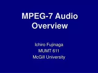
low medium high Channel bitrate(kbps) 2 4 6 8 10 12 14 16 24 32 48 64 ~ Scalable Coder Parametric coder CELP coder ~ T/F coder ITU-T coder Signal Bandwidth 4 kHz 8 kHz 20 kHz Assignment of codecs to bitrate ranges in MPEG-4 natural audio coding
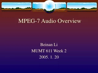
Audio in Analysis Filterbank Quantization & Coding Encoding of bitstream bistream out Perceptual Model Audio out bistream in Decoding of bitstream Inverse Quantization Synthesis Filterbank A basic perceptual audio coder Block diagram of a perceptual Encoding system Block diagram of a perceptual Decoding system
The absolute threshold of hearing in quiet • Across the audio spectrum, quantifies sound pressure level (SPL) required at each frequency such that an average listener will detect a pure tone stimulus in a noiseless environment
The absolute threshold of hearing in quiet • The absolute threshold of hearing characterizes the amount of energy needed in a pure tone such that it can be detected by a listener in a noiseless environment. • The absolute threshold is typically expressed in terms of dB Sound Pressure Level (dB SPL). • The quiet threshold is well approximated by the non-linear function
TEMPORAL MASKING • Pre-masking in particular has been exploited in conjunction with adaptive block size transform coding to compensate for pre-echo distortions.
Pre-echo effect • Pre-Echo Example: (a) Uncoded Castanets. (b) Transform Coded Castanets, 2048-Point Block Size
An iterative method is • employed • So as to keep the quantization • noise in all critical bands • below the global masking • threshold The building blocks of MPEG-2 AAC encoder • A high frequency resolution • filterbank (MDCT) • Switched between resolutions • of 1024 and 128 spectral lines • The shape of the transform • window can be adaptively • selected between a sine • window an a Kaiser-Bessel- • derived(KBD) window • Depending on the stationary • or transient character of the • input signal The temporal noise shaping tool controls the time dependence of the quantization noise the perceptual model is taken from MPEG-1(model 2). • The second-order backward • adaptive predictor • Improves coding efficiency .
Channel mapping • supports up to 46 channels for various multichannel loudspeaker configurations and other applications • the default loudspeaker configurations are • the monophonic channel • the stereophonic channel • the 5.1 system (five channels plus LFE channel).
Applications for MPEG-2 AAC • Due to its high coding efficiency, AAC is a prime candidate for any digital broadcasting system. • The Japanese authorities were the first to decide to use AAC within practically all digital audio broadcasting schemes. As their first services will start in the year 2000, this decision already triggered the development of dedicated AAC decoder chips at a number of manufacturers. • AAC has been selected for the use within the Digital Radio Mondiale (DRM) system. Due to its superior performance, AAC will also play a major role for the delivery of high-quality musicvia the Internet.
Applications for MPEG-2 AAC • Furthermore, AAC (with some modifications) is the only high-quality audio coding scheme used within the MPEG-4 standard, the future "global multimedia language". • Fraunhofer IIS-A offers to contribute to AAC applications at all implementation levels, e.g. licensing software libraries for PC-based applications or for VLSI developments as well as offering DSP-based solutions (e.g. on Motorola’s DSP56300, Texas Instruments’ TMS320C67xx, and Analog Devices’ ADSP21x6x family). The coding methods developed by Fraunhofer IIS-A stand for optimum audio quality at any given bit rate.
Profiles of MPEG-2 AAC (1) main profile •offers highest quality • used when memory cost is not significant • substantial processing power is available (2) low-complexity profile (LC) • used when RAM usage, processing power and compression requirements are all present • preprocessing and time-domain prediction are not permitted • TNS order and bandwidth are limited (3) scaleablesampling rate profile (SSR) • offers the lowest complexity • preprocessing block is added,and prediction is not permitted •TNS order and bandwidth are limited
Tool usage of AAC Profiles • Profile Interoperability
MPEG-2 AAC audio transport formats • the basic audio format and the transport syntax for synchronization and coding parameters in MPEG-1 are tied together unseparably • MPEG-2 AAC defines both,but leaves the actual choice of audio transport syntax to the application • ADIF (Audio Data Interchange Format) • puts all data controlling the decoder (like sampling frequency, mode etc.) into a single header preceding the actual audio stream • it is useful for file exchange , but does not allow for break-in or start of decoding at any point in time like the MPEG-1 format • ADTS (Audio Data Transport Stream) • format packs AAC data into frames with headers very similar to the MPEG-1 header format • allows start of decoding in the middle of an audio bitstream • the ADTS format has emerged as the de-facto standard for a number of applications using AAC
Filterbank and block switching • Standard Filterbank • A straight forward Modified Discrete Cosine Transform (MDCT) • Supporting block lengths of 2048 points and 256 points which can be switched dynamically • Supports two different window shapes that can be switched dynamically • sine shaped window • Kaiser-Bessel Derived (KBD) Window • All blocks are overlapped by 50% with the preceding and the following block
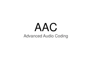
Frame k Frame k+1 Frame k+2 Frame k+3 M M M M MDCT MDCT MDCT MDCT M M MDCT M MDCT M M M 2M 2M 2M 2M 2M 2M + + ‧ ‧ ‧ ‧ ‧ ‧ M M Frame k+1 Frame k+2 MDCT & IMDCT • the MDCT basis functions extend across two blocks in time, leading to virtual elimination of the blocking artifacts
Temporal noise shaping (TNS) • The basic idea of TNS relies on the duality of time and frequency domain • TNS uses a prediction approach in the frequency domain to shape the quantization noise over time • It applies a filter to the original spectrum and quantizes this filtered signal • quantized filter coefficients are transmitted in the bitstream • the decoder undo the filtering performed in the encoder, leading to a temporally shaped distribution of quantization noise in the decoded audio signal
Frequency domain prediction • Improves redundancy reduction of stationary signal segments • Only supported in AAC Main • The actual implementation of the predictor is a second order backwards adaptive lattice structure • The required processing power of the frequency domain prediction and the sensitivity to numerical imperfections make this tool hard to use on fixed point platforms
Joint stereo coding • Mid-Side (MS) stereo coding • Applies a matrix to the left and right channel signals, computing sum and difference of the two original signals • Intensity stereo coding • Saving bitrate by replacing the left and the right signal by a single representing signal plus directional information • Intensity stereo is by definition a lossy coding method thus it is primarily useful at low bitrates. For coding at higher bitrates only MS stereo is used.
Scalefactors • Inherent noise shaping in the non-linear quantizer is usually not sufficient to achieve acceptable audio quality • Scalefactors are used to amplify the signal in certain spectral regions (the scalefactor bands) to increase the signal-to-noise ratio in these bands • To properly reconstruct the original spectral values in the decoder the scalefactors have to be transmitted within the bitstream • Scalefactors are coded as efficiently as possible • differentially encoded and then Huffman
Quantization • A non-linear quantizer is used • The main source of the bitrate reduction • It assignes a bit allocation to the spectral values according to the accuracy demands determined by the perceptual model • The main advantage over a conventional linear quantizer is the implicit noise shaping
11 huffman codebooks for the spectral data 2 huffman codebooks for the intensity stereo Noiseless coding • The noiseless coding tries to optimize the redundancy reduction within the spectral data coding • The spectral data is encoded using a Huffman code Neither spectral coefficients nor a scalefactor transmitted