Download
1 / 4
40 likes | 188 Views
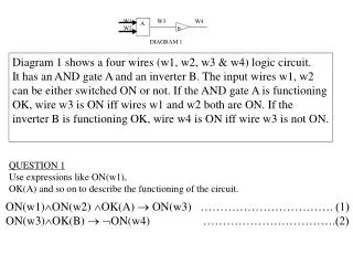
Diagram 1 shows a four wires (w1, w2, w3 & w4) logic circuit.

E N D
Diagram 1 shows a four wires (w1, w2, w3 & w4) logic circuit. It has an AND gate A and an inverter B. The input wires w1, w2 can be either switched ON or not. If the AND gate A is functioning OK, wire w3 is ON iff wires w1 and w2 both are ON. If the inverter B is functioning OK, wire w4 is ON iff wire w3 is not ON. QUESTION 1 Use expressions like ON(w1), OK(A) and so on to describe the functioning of the circuit. ON(w1)ON(w2) OK(A) ON(w3) ……………………………. (1) ON(w3)OK(B) ON(w4) …………………………….(2)
QUESTION 2 Using the formulas describing the functioning of the circuit and assuming that all components are functioning properly (OK) and that wires w1 and w2 are ON. Use resolution to show that w4 is not ON. Given that: OK(A) ……………………………(3) OK(B) …………………………….. (4) ON(w1) ……………………………..(5) ON(w2) ………………………………(6) From (5), (6) & (3): ON(w1) ON(w2) OK(A) ………………………..(7) From (1) & (7), using Modus Ponens: ON(w3) ………………………………………………(8) From (4) & (8): OK(B) ON(w3) ……………………………………. (9) From (2) & (9), using Modus Ponens: ON(w4) -- proven. ---------------------------------- (10)
QUESTION 3 Using the formulas developed in question 1 and that wires w1 and w2 are ON but wire w4 is also ON. Use resolution to show that either AND gate or inverter is not functioning properly.
Given that: ON(w1) …………………. (11) ON(w2) …………………. (12) ON(w4) …………………..(13) From (1): ON(w1)ON(w2)OK(A) ON(w3) …………………….. (14) From (2): ON(w3)OK(B)ON(w4) ………………………………... (15) Resolving (11) & (14) ON(w2)OK(A) ON(w3) …………………………………. (16) Resolving (16) & (12) OK(A) ON(w3) ………………………………………… (17) Resolving (15) & (17) OK(A) OK(B)ON(w4) ………………………………… (18) Resolving (18) & (13) OK(A) OK(B) ------------ proven!