Download

1 / 44
440 likes | 589 Views
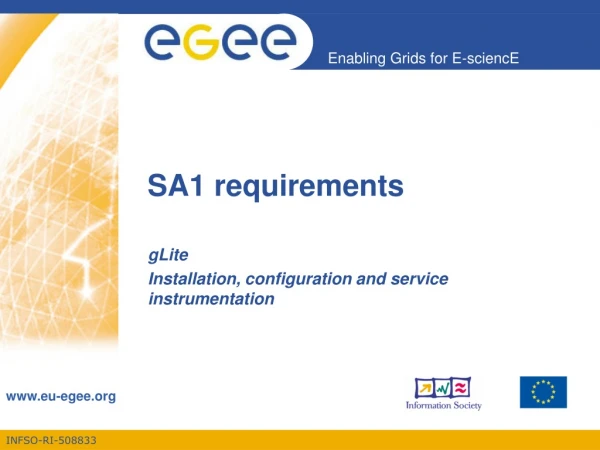
SA1 Network Infrastructure and QoS. Davide Adami, Franco Davoli CNIT d.adami@iet.unipi.it , franco@dist.unige.it 7th DORII AHM Meeting Stuttgart, Germany, March 2010. SA1 Objectives, Deliverables and Milestones (M24) SA1 Activity Status and Outcomes (M24)

E N D
SA1Network Infrastructure and QoS Davide Adami, Franco Davoli CNIT d.adami@iet.unipi.it, franco@dist.unige.it 7th DORII AHM Meeting Stuttgart, Germany, March 2010
SA1 Objectives, Deliverables and Milestones (M24) SA1 Activity Status and Outcomes (M24) Network Monitoring Platform Status Short-Term/Mid-Term Activity and Roadmap Outline
SA1 aims at the design and deployment of a network infrastructure tailored for DORII applications Partners: CNIT, GRNET, USTUTT Objectives: To investigate and define features of the network infrastructure, necessary to support a new form of cooperative and distributed utilization of resources, such as computing facilities and unique advanced instruments To provide specific networking infrastructure delivering advanced services to the scientific communities, including QoS and IPv6 support from GÉANT2 To select the best services in accordance to user requirements To design procedures able to detect and configure the network devices’ interfaces to better exploit the capabilities of the available networks SA1 Objectives
QoS requirements of DORII applications End-to-end QoS provisioning and users access networks’ features QoS support at NRENs’ level Mobility and security support GÉANT2 network services selection Mapping QoS requirements at application level into network services Mechanisms to interface user applications with the core infrastructure Test bed deployment Developing Service Level Specifications and Agreements Monitoring of the network with regard to SLA compliance Some Topics to be addressed
Overall schedule –SA1 & the Project Workplan AHM Stuttgart
Task 2. Use cases and access networks features (CNIT, GRNET) (M10) INPUT: Definition of use cases and application scenario OUTPUT: Guidelines for the deployment of grid applications Task 3. Selection of GÉANT network services and VPN definition (CNIT. GRNET) (M10) INPUT: Description of GÉANT network services OUTPUT: Mapping remote instrumentation services into GÉANT network services Task 4. Interfacing user-applications with the network infrastructure (CNIT, GRNET) (M18) INPUT: User access networks analysis OUTPUT: Design of mechanisms to interface user premises networks with the core infrastructure Task 5. Testbed implementation (CNIT, GRNET, USTUTT) (M18) INPUT: Testbed definition OUTPUT: Testbed deployment Task 6. Performance monitoring (CNIT, GRNET, USTUTT)(M27) INPUT: Experimental Scenario Definition OUTPUT: Traffic measurements and performance analysis Activity Description
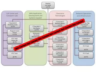
DORII CEs Connectivity Map ce01.ariagni.hellasgrid.gr clientRouter.hellasgrid05.access-link.grnet.gr Heraklio2-to-Syros.backbone.grnet.gr ce01.athena.hellasgrid.gr syros-to-eie1.backbone.grnet.gr clientRouter.hg-06-ekt.eie-2.access-link.grnet.gr ce01.isabella.grnet.gr GEANT grnet-gw.rt1.ath2.gr.geant2.net clientRouter.isabella.athens-3.access-link.grnet.gr ce01.marie.hellasgrid.gr as1.rt1.ath2.gr.geant2.net rediris-gw.rt1,mad.es.geant2.net kol1-to-eie2.backbone.grnet.gr clientRouter.grid-iasa.athens-3.access-link.grnet.gr NAC.AS0-0-0.EB-Bilbao0.red.rediris.es ath3-to-eie2.backbone.grnet.gr PAV.S00-0-0.EB-Santander0.red.rediris.es eie1-to-athens3.backbone.grnet.gr patra2-to-athens3.backbone.grnet.gr Ifca-router.red.rediris.es larissa2-to-eie1.backbone.grnet.gr clientRouter.hg-04-cti-ceid.patra2.access-link.grnet.gr thessaloniki2-to-larissa2.backbone.grnet.gr i2gce01.ifca.es egeece01.ifca.es clientRouter.grid-auth.thessaloniki2.access-link.grnet.gr ce01.kallisto.hellasgrid.gr ce01.afroditi.hellasgrid.gr
Task 6 Performance Monitoring Platform for Network Monitoring - http://monitor2.cnit.it Statistics are collected by using: Active Monitoring Tools Smokeping (also http://monitor2.cnit.it/cgi-bin/smokeping.cgi) for RTT Measurement Tool Pathload to estimate the available Bandwidth Passive Measurement Tools based on SNMP NAGIOS (also http://dorii.admin.grnet.gr/nagios/) MRTG NetFlow (http://netmon.grnet.gr/netflow)
Pathload_ sender: at DORII CE/SE sites GRNET, PSNC, CSIC-IFCA Pathload_receiver: at DORII IE/VCR sites EUCENTRE, OGS, ELETTRA, ECO-CdP, UC, Measurements are collected by CNIT at http://monitor2.cnit.it Pathload (Sender/Receiver) Senders Receivers • This way the bandwidth available from sites hosting CEs and SEs to sites with applications (IEs and VCR) is estimated
Pathload (How it works) Receiver Ie-01.eucentre.it TCP 55002 EUCENTRE 55001 UDP PSNC HTTP UDP Sender 150.254.161.225 55002 55001 HTTP Collector monitor2.cnit.it TCP Receiver eva.ogs.trieste.it OGS PSNC OGS Available Bandwidth March 1, 2010
Task 5 - TestbedIPv6 Network Support Native IPv6 Connectivity LMU USTUTT DFN PSNC PIONIER (IPv4) GRNET (IPv6) GEANT (IPv6 Transport Network) UC RedIRIS CSIC IPv4 Island OGS GARR (IPv6) EUCENTRE (IPv6) CNIT IPv4 Island ELETTRA Native IPv6
[root@ce01 ~]# traceroute6 2001:760:2000:2000::28 traceroute to 2001:760:2000:2000::28 (2001:760:2000:2000::28) from 2001:648:2030::1, 30 hops max, 16 byte packets 1 2001:648:2030::80 (2001:648:2030::80) 13.032 ms 0.558 ms 0.506 ms 2 grnetRouter.hg-05-forth.eie-2.access-link.grnet.gr (2001:648:2ffd:f037::1) 7.38 ms 2.64 ms 2.2 ms 3 Ath3.grnet.gr (2001:648:2fff:180::1) 10.474 ms * 9.861 ms 4 eie2-to-ath3.backbone.grnet.gr (2001:648:2fff:1103::1) 10.384 ms 9.318 ms 10.496 ms 5 grnet.rt1.ath2.gr.geant2.net (2001:798:19:10aa::1) 8.786 ms 9.759 ms 10.381 ms 6 as0.rt1.vie.at.geant2.net (2001:798:cc:1001:1901::5) 46.91 ms 46.255 ms 45.375 ms 7 so-3-0-0.rt1.mil.it.geant2.net (2001:798:cc:1001:1e01::2) 58.734 ms 58.878 ms 58.756 ms 8 garr-gw.rt1.mil.it.geant2.net (2001:798:1e:10aa::2) 57.593 ms 64.761 ms 59.224 ms 9 rt1-mi1-rt-mi3.mi3.garr.net (2001:760:ffff:ffff::f7) 59.648 ms 58.511 ms 58.767 ms 10 rt-mi3-rc-pv.pv.garr.net (2001:760:ffff:ffff::e5) 60.518 ms 59.175 ms 71.277 ms 11 rc-pv-ru-unipv.pv.garr.net (2001:760:ffff:16c::41) 60.101 ms 58.97 ms 59.53 ms 12 2001:760:2000::8 (2001:760:2000::8) 59.888 ms 60.672 ms 58.764 ms 13 2001:760:2000:2000::28 (2001:760:2000:2000::28) 58.987 ms 60.342 ms 60.697 ms [root@ce01 ~]# ping6 2001:760:2000:2000::28 PING 2001:760:2000:2000::28(2001:760:2000:2000::28) 56 data bytes 64 bytes from 2001:760:2000:2000::28: icmp_seq=0 ttl=52 time=58.7 ms 64 bytes from 2001:760:2000:2000::28: icmp_seq=1 ttl=52 time=59.7 ms 64 bytes from 2001:760:2000:2000::28: icmp_seq=2 ttl=52 time=58.8 ms 64 bytes from 2001:760:2000:2000::28: icmp_seq=3 ttl=52 time=59.5 ms 64 bytes from 2001:760:2000:2000::28: icmp_seq=4 ttl=52 time=58.8 ms 64 bytes from 2001:760:2000:2000::28: icmp_seq=5 ttl=52 time=58.8 ms --- 2001:760:2000:2000::28 ping statistics --- 6 packets transmitted, 6 received, 0% packet loss, time 5008ms rtt min/avg/max/mdev = 58.741/59.110/59.795/0.437 ms, pipe 2 IPv6 Reachability Test
DORII End-Hosts and Applications VCR, CE, IE, SE IPv6 Support
Performance monitoring Case Study
Performance Evaluation Methodology QoE Evaluation Test Definition Test Running Statistics vs. QoE Statistics Network Parameter Configuration Guidelines
EUCENTREEEWS Application se01.kallisto.hellasgrid.gr SE 2 wms01.grid.elettra.trieste.it 1 5 IE WMS 3 4 7 ie-01.eucentre.it 6 CE • 1, 2: Input Data Transfer • 3, 4: Job Submission • 5: : Data Retrieval • 6, 7: Output Data Transfer ce01. marie.hellasgrid.gr
EUCENTREEEWS Tests File Size: 116 MB from Ie-01.eucentre.it
EUCENTREEEWS Tests File Size: ~116 MB from se01.kallisto.hellasgrid.gr from wms01.grid.elettra.trieste.it
Performance requirement Execution Time (Computation Time + Data Transfer Time Data transfer time heavily affects the performance of the application High Data Transfer Time and low average throughput although the network is not congested Why low performance? WMS is an architectural bottleneck Which is the load on WMS, CE, SE, IE? How data transfers are carried out? Does the application have QoS requirements? Real-Time may require performance guarantees EEWS/EUCENTRE Design and Performance
Network Statistics SE (B,D) se01.isabella.grnet.gr wms01.grid.elettra.trieste.it D IE WMS D ce02.athena.hellasgrid.gr ie-01.eucentre.it (B, D) CE • D Delay • B Available Bandwidth • SNMP-enabled
SNMP Network Utilization ie-01.eucentre.it se01.kallisto.hellasgrid.gr.it ce01.marie.hellasgrid.it
OGS - GLIDER Platform (GLIDER) 1 Satellite 2 Ground Station 7 3 5 6 Instrument Element Storage Element Computing Element 4 8 VCR 9 Web Server User
OGS - FLOAT Platforms (FLOAT Sensors) 1 Satellite 2 Ground Station 7 3 5 6 Instrument Element Storage Element Computing Element 4 8 VCR 9 Web Server User
OGS - OPATM-BFM Physical Forcing Input Server 2 Computing Element 1 VCR Instrument Element 3 Storage Element 4 Web Server 5 User
This scenario deals with the users belonging to the oceanographic modeling community: they work with numerical models and with their data to get information about the past, the present or the future state of the marine environment or to study a specific process over limited space or time scales. Registration: the user has to apply to INFN for a personal certification. Login: the user opens the official DORII VCR page hosted by Elettra (https://dorii-vcr.grid.elettra.trieste.it/gridsphere/gridsphere) and asks for an account. Credential Management: once the user has both a valid certificate and a valid VCR account, he can upload the public and the private key to the VCR in order to create a valid proxy at each connection. Submit a job. The following actions are required: Take note of the CE (At present, Ce.reef.man.poznan.pl Take note of the job size, submission time, start/finish computation time Analyse the output produced by the CE and transferred to the SE(at present ce01.isabella.grnet.gr)and the standard output sent to the VCR. Take note of download time, start/finish time of the download Logout. OGS – OCON-MOONTest Description
UC - HORUS Case 2: Numerical Models with information coming from the camera stations Case 1: Algorithms testing User interface (VCR/gEclipse) Instrument Element (Input) Storage Element Input Storage Element FTP server Storage Element input Input 1 2 Computing Element Computing Element 3 2 Instrument Element User interface (VCR/gEclipse) Input Storage Element Output Storage Element Output
This scenario concerns users who aim at processing big amounts of data,either directly captured by the sensors or stored in a database. Sometimes data will be collected by a digital camera, sometimes data will come from all the cameras in a HORUS station. Registration: the user has to apply for a personal certification Login: the user opens the official DORII VCR page hosted by Elettra and asks for an account Credential Management: once the user has both a valid certificate and a valid VCR account, the user can upload the public and the private key to the VCR in order to create a valid proxy at each connection Data acquisition setup. The user selects the UC IE at http://puerpc79.caminos.unican.es and, more specifically, the desired IM with the database, the digital cameras, the sites, the sensors, etc. Data capture schema selection. The user selects the desired capture schema that depends on the instrument. Data capture execution. This way data are moved to a SE. Actions required: Take note of the SE. Take note of the File Size, Start and Finish Time UC – HORUSTest Description -1/2
Once the data are stored in the SE, two options are available: Submit a job to a CE, so as to process the captured data. Actions required: Take note of the CE. Take note of the Job Size, Submission Time, Start and Finish Computation Time. Run one of the predefined VCR applications over the captured data. Actions required Take note of the CE. Take note of the Start and Finish Time. When the selected jobs end, data are put into a SE and are available to be downloaded. If one performs this operation, the following actions are required: Take note of the SE. Take note of the File Size, Start and Finish Download Time. Logout UC – HORUSTest Description - 2/2
ELETTRA - SAXS 5 VCR 1 Instrument Element 2 Storage Element 3 4 User Computing Element SAXS (Small Angle X-ray Scattering)
There are three classes of users: a) internal lab user, who carries out the experiment and launches on-line processing; b) remote users, who visualize the results of the experiment and perform off-lime processing; c) developers, who performs both external and internal users’ tasks for testing purposes. Registration: the user has to apply to INFN for a personal certification. Login: the user opens the official DORII VCR page hosted by Elettra and asks for an account. Credential Management: once the user has both a valid certificate and a valid VCR account, the user can upload the public and the private key to the VCR in order to create a valid proxy at each connection. Use of tunnel resource: the user accesses remotely the beamline control panel, selects a tunnel resource to the beamline control panel and checks if everything is ok with the experiment setup. Action required: Take note of the time this operation is performed. Use of IE/IM, which moves the acquired data to a selected SE: the user selects the Instrument Detector and checks if it is turned on. If not, the user turns on the instrument which virtualizes the beamline detector. Actions required: Take note of the SE. Take note of the time this operation is performed. ELETTRA – SAXSTest Description -1/3
Use of the SE: the user browses the SEs to select the folder where data will be stored. Action required: Take note of the time this operation is performed. The user selects the application manager tab and launches the interactive online processing application. By using this application, the user determines a set of parameters for the online processing phase. An acquired image is selected, visualized and processed interactively. Action required: Take note of the time each operation is performed. On-line processing. The user selects the “start on-line processing application” using the parameters determined by the previous steps. The application jointly uses IE, CE, SE. Images are processed while they are acquired. Actions required: Take note of the IE, SE, CE Take note of the CE. Take note of the image size, number of images, download/upload time, start/finisch computation time. The user monitors that everything is working correctly by accessing a specific SE and visualizing the acquired images, and the processing results. Action required: Take note of the time this operation is performed. ELETTRA – SAXSTest Description -2/3
The user registers significant events in the logbook to facilitate teamwork. The user collaborates with the external users via chat, Skype and the other collaboration tools. The user stops the online processing: the user selects the stop online processing application using the parameters determined by the previous steps. The application collectively uses instruments and storage resources to stop the acquisition process and the online processing jobs exits. Action required: Take note of the time this operation is performed. 10. The user checks that the beamline is still working using the tunnel resource in order to prepare the beamline for the next user. The user logs out from the VCR. ELETTRA – SAXSTest Description -3/3
SA1 last deliverable entitled “Traffic Analysis and model synthesis of remote instrumentation” is due on April 30, 2010 What we have to do: For each application, following the “Performance Evaluation Methodology”, tests must be carried out Tests results should allow to evaluate the possibility of using QoS at network level to improve the performance of the applications Traffic statistics must also be collected when applications are running in a production infrastructure What is needed? Making arrangement on the test procedure to follow for each application Scheduling tests with applications Installing tcpdump/wireshark to get some traffic traces Roadmap and Future Activities
Classification of DORII applications based on network requirements Analysis and selection of network services to be deployed, if needed to improve DORII applications performance Deployment of the network monitoring infrastructure Deployment of the DORII IPv6 testbed Definition of a methodology to evaluate QoS vs. QoE for DORII applications Preliminary network performance analysis of DORII applications Major Outcomes Summary
Interfacing user-applications with the network infrastructure Network infrastructure could prevent applications to be used in a seamless flavour due to different core characteristics. For instance (a) access networks relying on highly asymmetrical transmission technologies may impede peering traffic (b) connectivity provided by mobile infrastructure or wireless systems (e.g., IEEE 802.11n or Wi-Max) may reflect in intermittent connections. In this vein, applications must be properly designed to detect and configure its network interfaces to better exploit the provided networking capabilities. Task 4