Download
1 / 17
170 likes | 277 Views
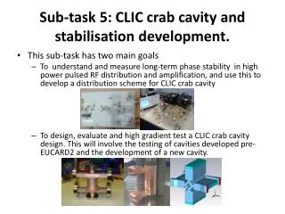
QD0 stabilisation in CLIC CDR. A.Jeremie with LAViSta team. What can be part of the CDR?. Introduction with specs: 0.1nm at 4Hz but can be revised with beam-feedback performance: Why: because detector moves much more than specs (CMS measurements?) Isolation from GM

E N D
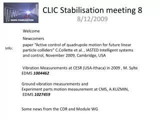
QD0 stabilisation in CLIC CDR A.Jeremie with LAViSta team
What can be part of the CDR? • Introduction with specs: 0.1nm at 4Hz but can be revised with beam-feedback performance: • Why: because detector moves much more than specs (CMS measurements?) • Isolation from GM • Compensation of resonance peaks • Feasibility already demonstrated (the successive PhDs) : • Isolation on commercial TMC table (x10) • Compensation of resonances with LAPP feedback (X3) • Tests done in laboratory environment • Feasibility to be demonstrated: • Isolation on compact device to fit in tight space • Has to work in magnetic field and radiation environment • How to integrate with the rest (cantilever or Gauss points) • Compatibility with beam feedback and pre-alignment • Modal analysis and vibration measurements on QD0 (here or in QDO part?) A.Jeremie MDI - CLIC CDR, May 7 2010
CMS top of Yoke measurement PSD of the signals Vertical direction Geophones Cooling system OFF PSD of the signals Beam direction 100 nm • Why: because detector moves much more than specs (CMS measurements?)
Introduction with specs: 0.1nm at 4Hz but can be revised with beam-feedback performance: Example of spectral analysis of different disturbance sources • Acoustic disturbance : • Ground motion : A pink noise on a large bandwidth Seismic motion Cultural noise • Amplified by the structure itself : the eigenfrequencies =>need to isolate and compensate
Some comments • Several PhDs: • C.Montag (DESY) 1997 • S.Redaelli (CERN) 2003 • B.Bolzon (LAPP) 2007 • M.Warden (Oxford) ~2010 • R. LeBreton (SYMME) ~2012 • Active vibration control is not yet a mature technology. • Activity should be defined as R&D but with CLIC engineering as objective. • It will take time to achieve the final objective but a work plan has been agreed with CDR as an important milestone. • Each time a new team starts this study, there is a non negligible “learning period”. Initially, only vertical direction was studied
Nanometer linac Stabilisation Feasibility already demonstrated : Isolation on commercial TMC table (x10) CLIC small quadrupole stabilised to nanometer level by active damping of natural floor vibration (S.Redaelli 2003) CERN vibration test stand passive active
Feasibility already demonstrated: compensation of resonances with LAPP feedback (X3) Cantilever FF stabilisation 2.5m FF Al mock-up LAPP active system for resonance rejection Resonance rejection Isolation CERN TMC active table for isolation • The two first resonances entirely rejected • Achieved integrated rms of 0.13nm at 5Hz (L.Brunetti et al, 2007)
Feasibility to be demonstrated: isolation on compact device to fit in tight space LAPP option Until now, the isolation function was studied on a TMC commercial active table: almost CLIC specifications but too big! (2.4mx0.9mx0.6m) S. Redaelli, CERN 2004 Approach: « Replace » TMC table by a more compact device And adding active isolation A.Jeremie MDI - CLIC CDR, May 7 2010 rms
Feasibility to be demonstrated: isolation on compact device to fit in tight space Option LAPP: Soft support (joint more for guidance thanreally « soft ») and active vibration control Rigid: less sensitive to external forces but less broadband damping Relative sensors (more compact) Soft elastomere joint in between 3 d.o.f. : actuators A.Jeremie MDI - CLIC CDR, May 7 2010
Status: Construction + tests on elastomer A.Jeremie MDI - CLIC CDR, May 7 2010
Feasibility to be demonstrated: has to work in magnetic field and radiation environment Sensors that can measure nanometres Absolute velocity/acceleration studied at LAPP: Sub-nanometremeasurements Relative displacement/velocity: CERN test bench : membrane and interferometer Capacitive gauges :Best resolution 10 pm (PI) , 0 Hz to several kHz Linear encoders best resolution 1 nm (Heidenhain) Vibrometers (Polytec) ~1nm at 15 Hz Interferometers (SIOS, Renishaw, Attocube) <1 nm at 1 Hz OXFORD MONALISA (laser interferometry) Optical distance meters Compact Straightness Monitors (target 1 nm at 1 Hz) • ATF2 vibration and vacuum test • Validation • Next: optical test A.Jeremie MDI - CLIC CDR, May 7 2010
Güralp CMG-40T Sensor type: electromagneticgeophonebroadband Signal: velocityx,y,z Sensitivity: 1600V/m/s Frequency range: 0,033-50Hz Mass: 7,5kg Radiation: Feedback loopso no Magneticfield: no Feedback loop First resonance 440Hz Temperaturesensitivity: 0,6V/10°C Electronic noise measuredat >5Hz: 0,05nm Stable calibration A.Jeremie MDI - CLIC CDR, May 7 2010
Endevco 86 Sensor type: piezoelectricaccelerometer Signal: acceleration z Sensitivity: 10V/g Frequency range: 0,01-100Hz but usefulfrom 7Hz Mass: 771g Radiation: piezo OK, but resin? Magneticfield: probably OK but acoustic vibrations? Feedback loop First resonance 370Hz Temperaturesensitivity: <1% Electronic noise measuredat >5Hz: 0,25nm, >50Hz 0,02nm Stable calibration, flat response Doesn’tlikeshocks A.Jeremie MDI - CLIC CDR, May 7 2010
SP500 Sensor type: electrochemical, specialelectrolyte Signal: velocity Sensitivity: 20000V/m/s Frequency range: 0,016-75Hz Mass: 750g Radiation: no effectaroundBaBar (don’t know exact conditions) Magneticfield: tested in 1T magnet => samecoherence, amplitude? Feedback loop First resonance >200Hz Electronic noise measuredat >5Hz: 0,05nm Unstable calibration, response not flat Robust A.Jeremie MDI - CLIC CDR, May 7 2010
How to integrate with the rest (cantilever or Gauss points) Gauss points option Cantilever option A.Jeremie MDI - CLIC CDR, May 7 2010
L.Pacquet, G. Deleglise Modal analysis and vibration measurements on QD0 Preliminary FF calculationsjust preliminary tests to get a feeling of what is going on…the numbers are not optimized Solid block without coils : 991Hz Cantilever : 125Hz 2 supports under magnet : 249Hz Solid block with mass of coils : 557Hz Work started with separate coils A.Jeremie MDI - CLIC CDR, May 7 2010
Test program at LAPP: • Currently: tests on a sensor borrowed from micro-epsilon (CS601-0.05) on a dedicated test set-up. • Have to give back end of this week • Preliminary results show that a nanometre movement can be measured by the sensor • Bought a sensor from PI (D-015): Just received! , complete (not quick and dirty like currently on borrowed sensor) for about a month. Then if OK, we will buy 3 more: receive this summer. Then tests on isolation device can start. • Study elastomere : shape (recent tests are difficult to interpret, need a better study) and fabrication process: unique piece vs separate rings) • Optimise Absolute sensor position • Optimise Passive material position • Work on FF magnet. Difficult before CDR! A.Jeremie MDI - CLIC CDR, May 7 2010