
Coordinating Multiple Nodes: MAC Protocols & Channelization
E N D
Presentation Transcript
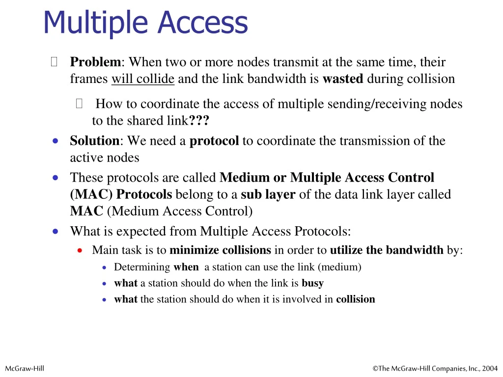
Problem: When two or more nodes transmit at the same time, their frames will collide and the link bandwidth is wasted during collision How to coordinate the access of multiple sending/receiving nodes to the shared link??? Solution: We need a protocol to coordinate the transmission of the active nodes These protocols are called Medium or Multiple Access Control (MAC) Protocols belong to a sub layer of the data link layer called MAC (Medium Access Control) What is expected from Multiple Access Protocols: Main task is to minimize collisions in order to utilize the bandwidth by: Determining when a station can use the link (medium) what a station should do when the link is busy what the station should do when it is involved in collision Multiple Access
Figure 12.2 Taxonomy of multiple-access protocols discussed in this chapter For wireless not included with us
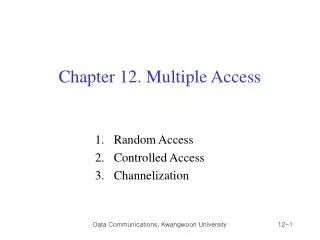
Random Access (or contention) Protocols: No station is superior to another station and none is assigned the control over another. A station with a frame to be transmitted can use the link directly based on a procedure defined by the protocol to make a decision on whether or not to send. Controlled access or scheduling: Provides in order access to shared medium so that every station has chance to transfer (fair protocol) Eliminates collision completely Three methods for controlled access: Reservation Polling Token Passing Random Access
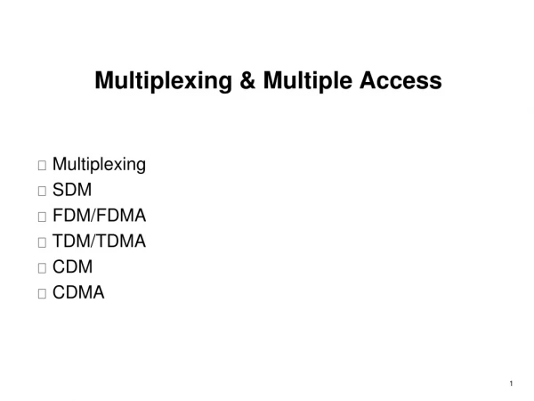
12-3 CHANNELIZATION Channelization is a multiple-access method in which the available bandwidth of a link is shared in time, frequency, or through code, between different stations. In this section, we discuss three channelization protocols. Topics discussed in this section: Frequency-Division Multiple Access (FDMA)Time-Division Multiple Access (TDMA) Code-Division Multiple Access (CDMA)
FDMA: Frequency Division Multiple Access: In frequency-division multiple access (FDMA), the available bandwidth is divided into frequency bands. Transmission medium is divided into M separate frequency bands Each station is allocated a band to send its data. Each station transmits continuously on the assigned band at an average rate of R/M. In other words, each band is reserved for a specific station, and it belongs to the station all the time. A node is limited to an average rate equal R/M (where M is number of nodes) even when it is the only node with frame to be sent. Each station also uses a band pass filter to confine the transmitter frequencies. To prevent station interferences, the allocated bands are separated from one another by small guard bands. In FDMA, the available bandwidth of the common channel is divided into bands that are separated by guard bands. 12-3 CHANNELIZATION - FDMA
The differences between FDMA and FDM • FDM is a physical layer technique that combines the loads from low-bandwidth channels and transmits them by using a high-bandwidth channel. • The channels that are combined are low-pass. • The multiplexer modulates the signals, combines them, and creates a band pass signal. The bandwidth of each channel is shifted by the multiplexer. • FDMA, on the other hand, is an access method in the data link layer. • The data link layer in each station tells its physical layer to make a band pass signal from the data passed to it. The signal must be created in the allocated band. • There is no physical multiplexer at the physical layer. The signals created at each station are automatically band pass-filtered. They are mixed when they are sent to the common channel.
TDMA: Time Division Multiple Access In time-division multiple access (TDMA), the stations share the bandwidth of the channel in time. Each station is allocated a time slot during which it can send data. The entire bandwidth capacity is a single channel with its capacity shared in time between M stations A node must always wait for its turn until its slot time arrives even when it is the only node with frames to send A node is limited to an average rate equal R/M (where M is number of nodes) even when it is the only node with frame to be sent 12-3 CHANNELIZATION - TDMA
Synchronization in TDMA • The main problem with TDMA lies in achieving synchronization between the different stations. • Each station needs to know the beginning of its slot and the location of its slot. • This may be difficult because of propagation delays introduced in the system if the stations are spread over a large area. To compensate for the delays, we can insert guard times. • Synchronization is normally accomplished by having some synchronization bits (normally referred to as preamble bits) at the beginning of each slot. • In TDMA, the bandwidth is just one channel that is timeshared between different stations.
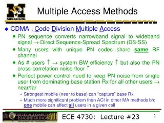
12-3 CHANNELIZATION - CDMA • CDMA: Code Division Multiple Access • In CDMA, one channelcarries all transmissions simultaneously • Each station codes its data signal by a specific codes before transmission • The stations receivers use these codes to recover the data for the desired station. • Example: • Let us assume we have four stations, 1, 2, 3, and 4, connected to the same channel. The data from station 1 are d1, from station 2 are d2, and so on. The code assigned to the first station is c1, to the second is c2, and so on. • If we multiply each code by another, we get 0. • If we multiply each code by itself, we get 4 (the number of stations). • Transmission • Station 1 multiplies (a special kind of multiplication, as we will see) its data by its code to get d1 ⋅ c1. • Station 2 multiplies its data by its code to get d2 ⋅ c2, and so on.
Channel The data that go on the channel are the sum of all these terms. Reception Any station that wants to receive data from one of the other three, it multiplies the data on the channel by the code of the sender. For example, suppose stations 1 and 2 are talking to each other. Station 2 wants to hear what station 1 is saying. It multiplies the data on the channel by c1, the code of station 1. Because (c1 ⋅ c1) is 4, but (c2 ⋅ c1), (c3 ⋅ c1), and (c4 ⋅ c1) are all 0s, station 2 divides the result by 4 to get the data from the station 1. Chips CDMA is based on coding theory. Each station is assigned a code, which is a sequence of numbers called chips. 12-3 CHANNELIZATION - CDMA
Properties of the Chip Sequences Each sequence is made of N elements, where N is the number of stations. Multiplication of a chip sequence by a scalar If we multiply a sequence by a number, every element in the sequence is multiplied by that element. This is called multiplication of a sequence by a scalar. Multiplication of two chip sequences If we multiply two equal sequences, element by element, and add the results, we get N, where N is the number of elements in each sequence. This is called the inner product of two equal sequences. If we multiply two different sequences, element by element, and add the results, we get 0. This is called the inner product of two different sequences. 12-3 CHANNELIZATION - CDMA
Adding two sequences means adding the corresponding elements. The result is another sequence. Data Representation/Encoding in CDMA If a station needs to send a 0 bit, it encodes it as −1; If it needs to send a 1 bit, it encodes it as +1. When a station is idle, it sends no signal, which is interpreted as a 0. 12-3 CHANNELIZATION - CDMA
We assume that stations 1 and 2 are sending a 0 bit and channel 4 is sending a 1 bit. Station 3 is silent. 12-3 CHANNELIZATION - CDMA
The Walsh table is a two dimensional table with equal number of rows and columns. Each row in the Walsh table is the one chip sequence. The number of sequences in a Walsh table must be: 12-3 Generating Chip Sequences –Walsh Table